Test handler

a handler and handle technology, applied in the field of test handlers, can solve the problems of unsuitable the above-cited problem relevant to thermal expansion or contraction, and the problem of not being able to achieve the appropriate contact between the two, etc., and achieve the effect of solving the problem of even more serious problems, yet to be solved

Active Publication Date: 2011-04-12
TECHWING CO LTD
View PDF8 Cites 2 Cited by
  • Summary
  • Abstract
  • Description
  • Claims
  • Application Information

AI Technical Summary

Benefits of technology

[0029]It is, therefore, an object of the present invention to provide a technology capable of compensating a deviation between test trays and match plates resulted from their thermal expansions or contractions, thus allowing semiconductor devices held by the test trays to be appropriately connected with test sockets of a tester regardless of the thermal expansions or contractions of the test trays and the match plates.
[0032]According to the present invention, by adjusting the positions of at least one of the test trays or the match plates, an appropriate connection between the semiconductor devices held by the test trays and the test sockets of the Hi-Fix boards can be achieved.

Problems solved by technology

In the above conventional configuration, however, as the sizes of the match plates 163a and 163b and the test trays 11a and 11b are changed due to their thermal expansions or contractions, an appropriate contact therebetween might not be achieved.
Besides, when considering the recent trend for the development of the test handler that the sizes of the test tray is increased to test more semiconductor devices at one time, the above-cited problem relevant to thermal expansion or contraction would become an even more serious problem yet to be solved.

Method used


Image

  • Test handler
  • Test handler
  • Test handler

Examples


first embodiment

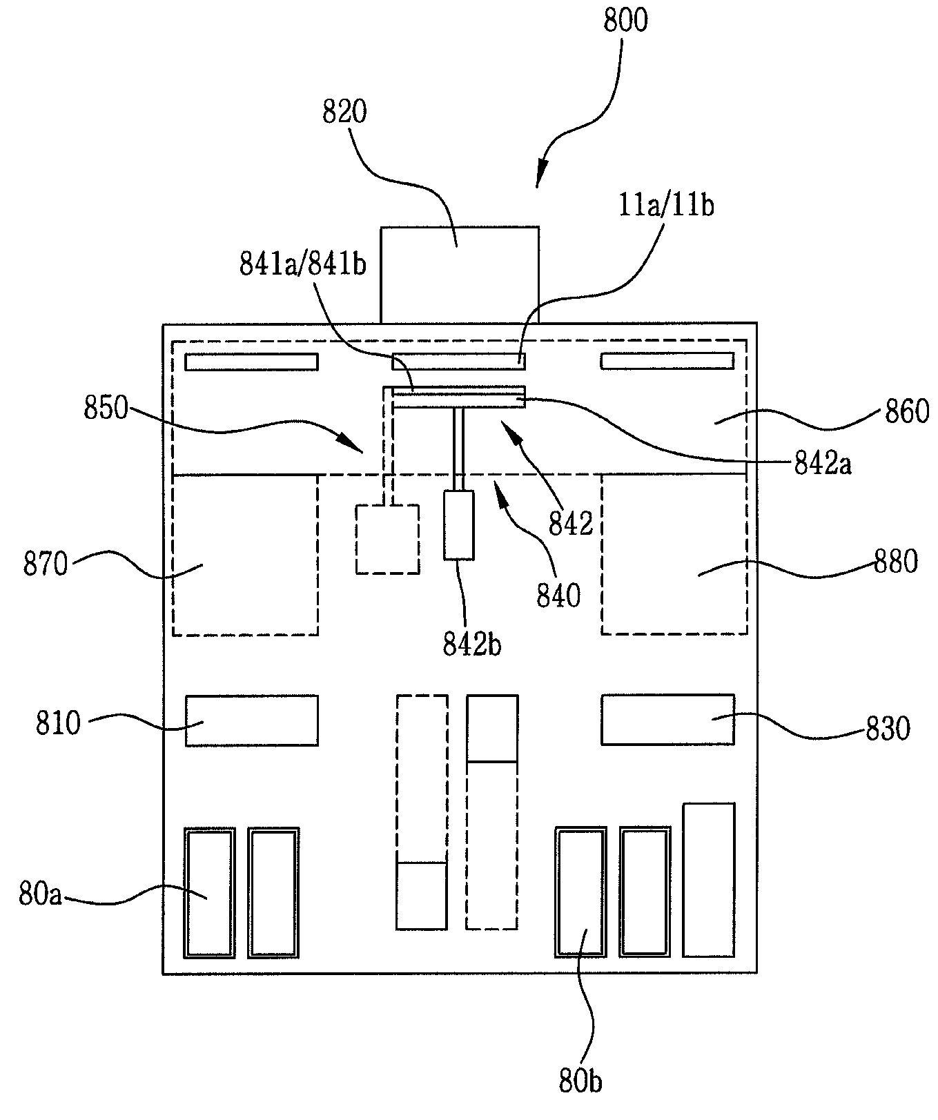
[0047]A test handler in accordance with a first embodiment of the present invention employs a mechanism for compensating a deviation between test trays and match plates by adjusting the positions of the match plates when deformations of test trays and the match plates occur due to thermal expansions or contractions thereof and when the deviation between them falls outside a tolerance range so that an appropriate connection between semiconductor devices held by the test tray and test sockets cannot be obtained.

[0048]FIG. 10 is a conceptual top view of a test handler 800 in accordance with the first embodiment. The test handler 800 includes a loading unit 810, a soak chamber 870, a test chamber 860, a desoak chamber 880, an unloading unit 830, a pushing unit 840, a position control unit 850, and so forth. The loading unit 810 loads semiconductor devices onto a test tray from customer trays 80a.

[0049]The soak chamber 870 is installed to pre-heat or pre-cool the semiconductor devices a...

second embodiment

[0074]Though a second embodiment of the present invention is based on the same principle as that of the first embodiment, it differs from the first embodiment in that an appropriate connection between semiconductor devices held by test tray and test sockets is achieved by adjusting the positions of the test trays, not the match plates. Here, it is assumed that the match plates do not undergo thermal deformation but only the test trays suffer thermal expansion or contraction for the simplicity of the explanation.

[0075]Referring to FIG. 16, each of move rails 1210a to 1210c serving as movement guide members and support members of test trays 11a and 11b is provided with an obliquely elongated hole 1210-1 and a vertically elongated hole 1210-2. Further, pulleys 1220a to 1220c are rotatably installed at coupling members 1230a to 1230c, respectively, wherein each pulley has an eccentric cam 1220-1 inserted into corresponding one of the vertically elongated holes 1210-2.

[0076]Each of the c...


PUM


Abstract

A test handler includes a loading unit for loading semiconductor devices from customer trays onto a test tray; a test chamber for performing a test for the semiconductor devices loaded on the test tray; a pushing unit having at least one pushing member for pushing the test tray located in the test chamber to be tested, and a press unit for operating the pushing member; a position control unit for adjusting a position of the pushing member to compensate a deviation between the pushing member and the test tray due to a thermal expansion or contraction of any one of the pushing member and the test tray; and an unloading unit for unloading the semiconductor devices loaded on the test tray onto the customer trays after a test for the semiconductor devices is completed.

Description

[0001]This application is a Continuation Application of PCT International Application No. PCT / KR2007 / 000371 filed on Jan. 22, 2007, which designated the United States.FIELD OF THE INVENTION[0002]The present invention relates to a test handler.BACKGROUND OF THE INVENTION[0003]In general, a test handler is an apparatus for supporting a tester for testing semiconductor devices fabricated through a preset manufacturing process. The test handler classifies the fabricated semiconductor devices into several classes according to their test results and serves to unload those classified semiconductor devices onto customer trays. Such a test hander has been already known through various published documents.[0004]FIG. 1 shows a schematic perspective view of a conventional test hander 100, and FIG. 2 sets forth a conceptual top view showing major components of the test handler 100. Below, the major components of the conventional test handler 100 will be described schematically with reference to ...

Claims


Application Information

Patent Timeline
Patent Type & Authority Patents(United States)
IPC IPC(8): G01R31/28
CPCG01R31/2893E05C17/44E05Y2900/132
Inventor SHIM, JAE GYUNNA, YUN SUNGJEON, IN GUKU, TAE HUNGKIM, DONG HAN
Owner TECHWING CO LTD
Why Eureka
Try Eureka