Method of fuel nozzle construction

a technology of fuel injection nozzles and fuel injection nozzles, which is applied in the direction of combustion types, lighting and heating apparatus, soldering apparatus, etc., can solve the problems of reducing engine performance, prone to insufficient flow, and prone to carbon formation or coking of stagnant fuel located within the main fuel circui

Active Publication Date: 2011-04-19
ROLLS ROYCE PLC
View PDF24 Cites 33 Cited by
  • Summary
  • Abstract
  • Description
  • Claims
  • Application Information

AI Technical Summary

Benefits of technology

[0015]The step of joining includes applying a standard vacuum braze cycle to the braze, or any other suitable process. The step of joining can include utilizing interference fitting of the first and second nozzle components to prevent formation of eutectic phases in the braze.

Problems solved by technology

One difficulty associated with operating a staged fuel injector is that when the pilot fuel circuit is operating alone during low power operation, stagnant fuel located within the main fuel circuit can be susceptible to carbon formation or coking due to the temperatures associated with the operating environment.
This can degrade engine performance over time.
However, when using traditional brazing techniques, the braze alloy must flow from a ring or pocket to the braze area.
In doing so, it is prone to flow imprecisely when melted.
In some instances intricate or narrow passages can become plugged if too much braze is used.
These fillets and plugs can negatively affect nozzle performance.
Moreover, braze may not flow to the desired braze area in the quantity needed to ensure a proper braze joint.
This is typical when the braze alloy cannot be located in close proximity to the desired braze joint location.
The difficulty in controlling braze flow employing traditional brazing techniques is a limiting factor in the design of fuel and air flow passages within a nozzle.
That is, the shape and size of the flow passages is limited by the ability to control the flow of braze.

Method used


Image

  • Method of fuel nozzle construction
  • Method of fuel nozzle construction
  • Method of fuel nozzle construction

Examples


Embodiment Construction

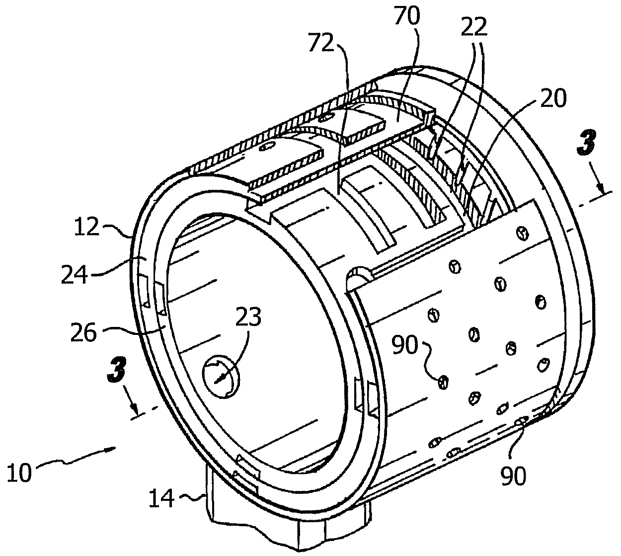
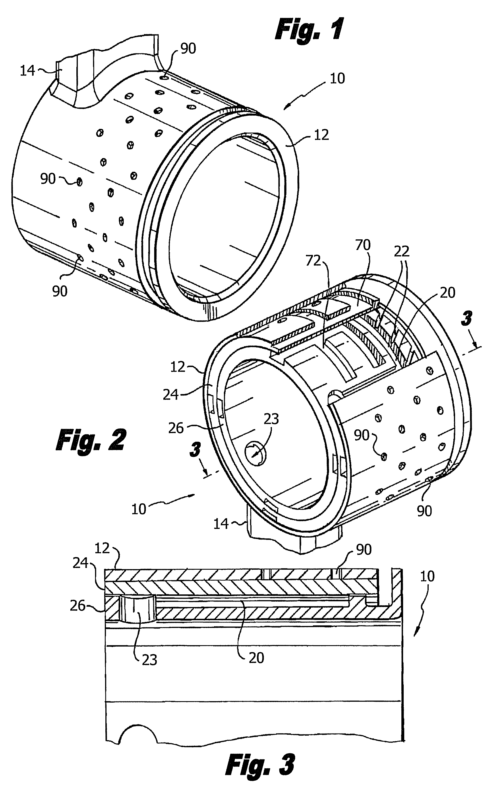
[0025]Reference will now be made to the drawings wherein like reference numerals identify similar structural features or aspects of the subject invention. In accordance with the invention, a fuel nozzle includes a first cylindrical nozzle component, a second cylindrical nozzle component disposed with an interference fit on an outward surface of the first nozzle component, and a layer of braze joiningly disposed between the first and second nozzle components. For purposes of example and not limitation, there is illustrated in FIG. 1 a portion of a fuel injector nozzle constructed in accordance with a preferred embodiment of the subject invention and designated generally by reference numeral 10. Fuel injector 10 is adapted and configured for delivering fuel to the combustion chamber of a gas turbine engine.

[0026]Referring to FIG. 2, fuel injector 10 is generally referred to as a staged fuel injector in that it includes a primary, or pilot fuel circuit 72, which typically operates duri...


PUM

PropertyMeasurementUnit
thicknessaaaaaaaaaa
thicknessaaaaaaaaaa
diameteraaaaaaaaaa

Abstract

A method of assembling a fuel nozzle includes providing a first nozzle component and a second nozzle component, wherein the first nozzle component is configured and adapted to engage within the second nozzle component. Braze is applied to at least one of the first and second nozzle components. The first nozzle component is assembled into the second nozzle component to provide a diametral interference fit therebetween. The method further includes joining the first and second nozzle components together. A fuel nozzle includes a first cylindrical nozzle component, a second cylindrical nozzle component disposed with an interference fit on an outward surface of the first nozzle component, and a layer of braze joiningly disposed between the first and second nozzle components.

Description

BACKGROUND OF THE INVENTION[0001]1. Field of the Invention[0002]The subject invention is directed to fuel injection nozzles for gas turbine engines, and more particularly, to a system and method for assembling components of fuel nozzles.[0003]2. Background of the Related Art[0004]Staged fuel injectors for gas turbine engines are well know in the art. They typically include a pilot fuel atomizer for use during engine ignition and low power engine operation and at least one main fuel atomizer for use during high power engine operation in concert with the pilot fuel atomizer. One difficulty associated with operating a staged fuel injector is that when the pilot fuel circuit is operating alone during low power operation, stagnant fuel located within the main fuel circuit can be susceptible to carbon formation or coking due to the temperatures associated with the operating environment. This can degrade engine performance over time.[0005]In the past, attempts were made to passively insula...

Claims


Application Information

Patent Timeline
Patent Type & Authority Patents(United States)
IPC IPC(8): B21D51/16B23K9/00B23P17/00B23P11/02
CPCF23D11/36F23R3/28F23R3/343F23D2213/00Y10T29/494Y10T29/49865Y10T29/49432Y10T29/49425F23R2900/00017
Inventor THOMSON, NEALCLAUSEN, DERRICKGROENEVELD, KEVIN
Owner ROLLS ROYCE PLC
Why Eureka
Try Eureka