
Image reproducing apparatus and method of controlling the image reproducing apparatus

a technology which is applied in the field of image reproducing apparatus and control method, can solve the problems of inability to use the user's large hand, inability to expand the space of the operation icon, etc., and achieve the effect of improving operability

Active Publication Date: 2011-04-19
CANON KK
View PDF12 Cites 5 Cited by
  • Summary
  • Abstract
  • Description
  • Claims
  • Application Information

AI Technical Summary

Benefits of technology

The present invention is about an image reproducing apparatus with a touch panel that improves operability. The apparatus detects when the external equipment is connected and displays an enlarged operation icon on the touch panel accordingly. This makes it easier for the user to operate the touch panel and perform touch-typing. Additionally, the invention prevents the operation icon from becoming enlarged when equipment other than image displaying equipment is connected. The technical effects of the invention are improved operability and ease of use for the user.

Problems solved by technology

Since a user needs to operate the touch panel while checking an image, a space of an operation icon is inevitably small and is not user-friendly for the user having a larger hand.

Method used


Image

  • Image reproducing apparatus and method of controlling the image reproducing apparatus
  • Image reproducing apparatus and method of controlling the image reproducing apparatus
  • Image reproducing apparatus and method of controlling the image reproducing apparatus

Examples


first exemplary embodiment

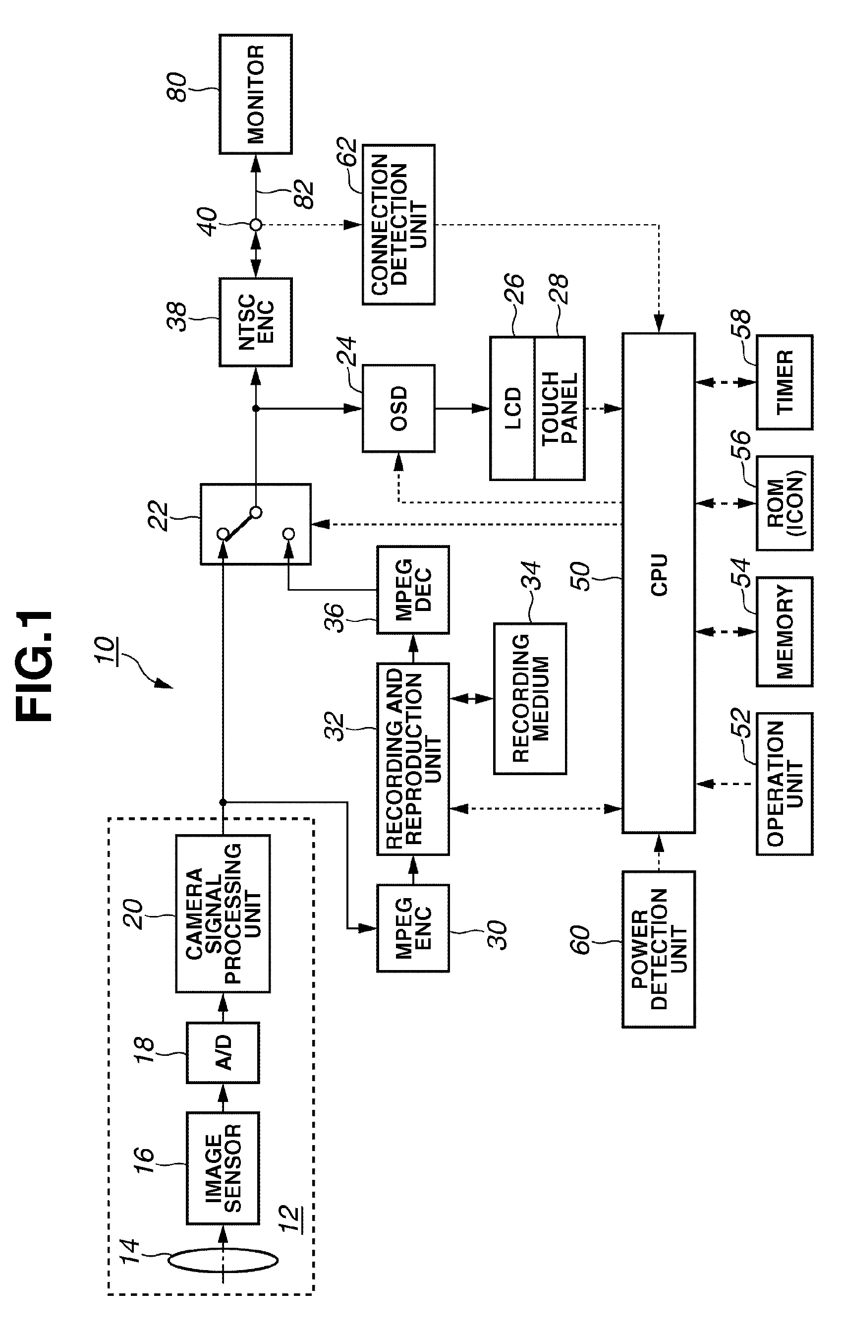
[0029]FIG. 1 illustrates a block diagram of an imaging apparatus according to a first exemplary embodiment of the present invention. In FIG. 1, a solid line represents a flow of image data and a broken line represents a flow of a control signal such as an enable signal. It is also noted that an audio processing system, which is not related to the present invention, is omitted from the illustration.

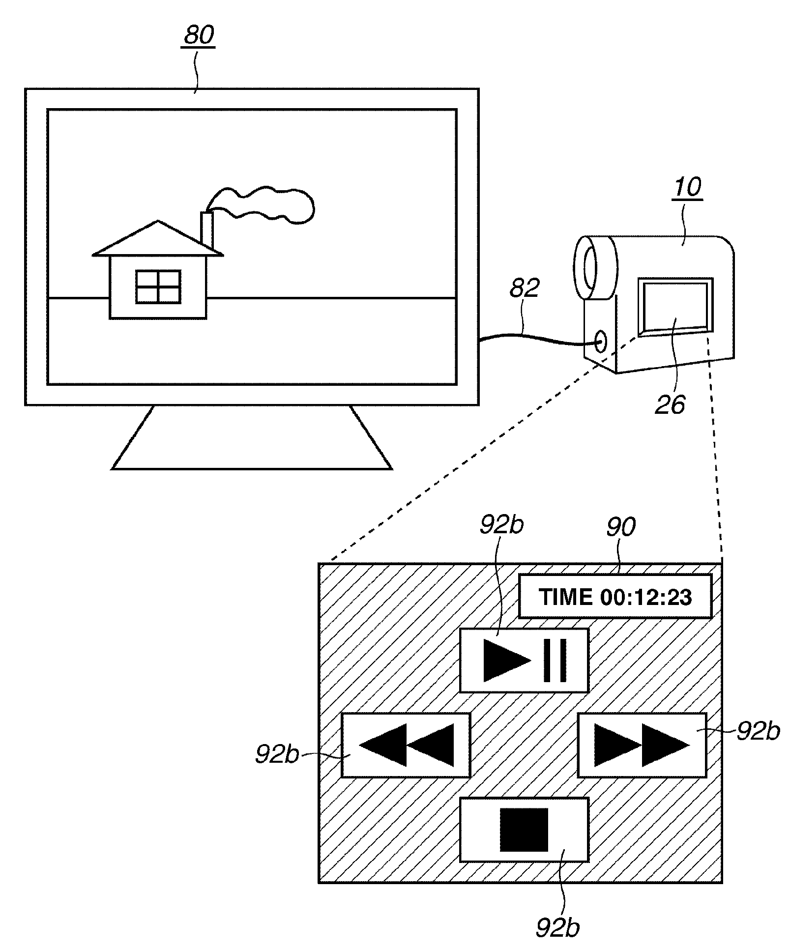
[0030]An imaging apparatus 10 is, for example, a digital video camcorder or a digital still camera. A video monitor 80 or an image monitor adapted to display a reproduced image is connected to the imaging apparatus 10 via a digital cable 82.

[0031]The imaging apparatus 10 includes an imaging unit 12, that is, a shooting lens 14, an image sensor 16, an analog to digital (A / D) converter 18 and a camera signal processing unit 20. The shooting lens 14 forms an optical image of a subject on the image sensor 16. The image sensor 16 converts the optical image taken by the shooting lens 14 into an ...

second exemplary embodiment

[0055]FIG. 7 illustrates a block diagram of an imaging apparatus according to a second exemplary embodiment of the present invention. The components similar to those in FIG. 1 are denoted by the same reference numerals.

[0056]An imaging apparatus 110 illustrated in FIG. 7 includes an Institute of Electrical and Electronic Engineers (IEEE) 1394 interface 112 and a connection terminal 114 of the IEEE 1394 interface in addition to the components of the imaging apparatus 10. An output signal selected by the selector 22 is supplied to the IEEE 1394 interface 112. A CPU 150 has a communicating function with an IEEE 1394 device through the IEEE 1394 interface 112 in addition to the control function of the CPU 50.

[0057]A video monitor 120 or an image monitor is connected to the connection terminal 114. The video monitor 120 includes a CPU 124 adapted to control an IEEE 1394 interface 122 and the video monitor 120. The CPU 124 is capable of communicating with other IEEE 1394 device (i.e., the...


PUM


Abstract

An image reproducing apparatus includes a selector which selects output of the MPEG decoder in a reproducing mode. A connection detection unit detects whether a video monitor is connected to an output terminal and a result of the detection is sent to a CPU. When a video monitor is connected, the CPU reads out bit map data of an operation icon having an enlarged size from a ROM and sends the data to an OSD control unit. The OSD control unit determines whether a blue background is displayed on a touch panel. If the operation icon is not enlarged, the OSD control unit masks a background portion with a single color (for example, blue background) and displays an enlarged operation icon over the background portion.

Description

BACKGROUND OF THE INVENTION[0001]1. Field of the Invention[0002]The present invention relates to an image reproducing apparatus and a controlling method. More particularly, the present invention relates to an image reproducing apparatus having a touch panel, and a controlling method therefor.[0003]2. Description of the Related Art[0004]In recent years, widespread use of touch panels has led electronics manufacturers to adopt a touch screen as a user interface component of electronic equipment. A liquid crystal display having a touch screen eliminates a need for a mechanical operation button since the operation button is displayed on the liquid display panel that is integrated with the touch panel, and thus contributes to providing a space-saving design of the electronic equipment. Accordingly, touch panels are advantageous especially when used in small electronic equipment. The touch panels are also convenient since an arrangement of operation buttons on the touch panel screen can b...

Claims


Application Information

Patent Timeline
Patent Type & Authority Patents(United States)
IPC IPC(8): H04N5/222G06F3/041H04N5/225H04N5/765
CPCH04N5/232H04N5/23216H04N5/772H04N9/8042H04N5/85H04N5/907H04N5/782H04N23/62H04N23/631
Inventor MATSUMOTO, SHINYA
Owner CANON KK
Learn More