Imaging apparatus

a technology of imaging apparatus and base, which is applied in the field of imaging apparatus, can solve the problems of affecting the downsizing of the whole imaging apparatus, and limiting the width of the camera unit, so as to stabilize the horizontal rotation of the camera frame, reduce the downsizing of the base, and improve the weight balance

Inactive Publication Date: 2011-04-19
ELMO CO LTD
View PDF8 Cites 14 Cited by
  • Summary
  • Abstract
  • Description
  • Claims
  • Application Information

AI Technical Summary

Benefits of technology

[0011]In the imaging apparatus of the invention having the configuration described above, the pivot support structure placed in the base pivotally supports the camera frame on the base. The vertical rotation transmission mechanism placed in the base transmits the driving force for the pivotal rotation of the camera frame in the vertical direction to the camera frame via the arc-shaped frame side face. The driving system involved in the vertical pivotal rotation of the camera frame about the axis passing through the inside of the camera frame in the direction parallel to the width of the camera frame is accordingly not located in either side of the camera frame. This arrangement desirably attains the space saving in the periphery of the camera frame.
[0023]In one preferable application, the horizontal rotation driving source and the vertical rotation driving source are arranged in the attitude having the respective output axis s in the horizontal direction and are disposed to face each other across the plate mounting structure on the pedestal plate. This arrangement gives the good weight balance to the pedestal plate and accordingly stabilizes the horizontal rotation of the camera frame. The driving source generally has the greater length in the direction of the output shaft than the length in the direction perpendicular to the output shaft. The arrangement of the two driving sources in the attitude having the respective output shafts in the horizontal direction accordingly has the space-saving effect. This concentrated arrangement contributes to the further downsizing of the base.

Problems solved by technology

However, the layout of placing the vertical pivot axis and the control circuit substrate on the opposed sides of the camera unit has certain limitation in downsizing along the width of the camera unit.
The large-size driving source interferes with downsizing of the whole imaging apparatus.

Method used


Image

  • Imaging apparatus
  • Imaging apparatus
  • Imaging apparatus

Examples


Embodiment Construction

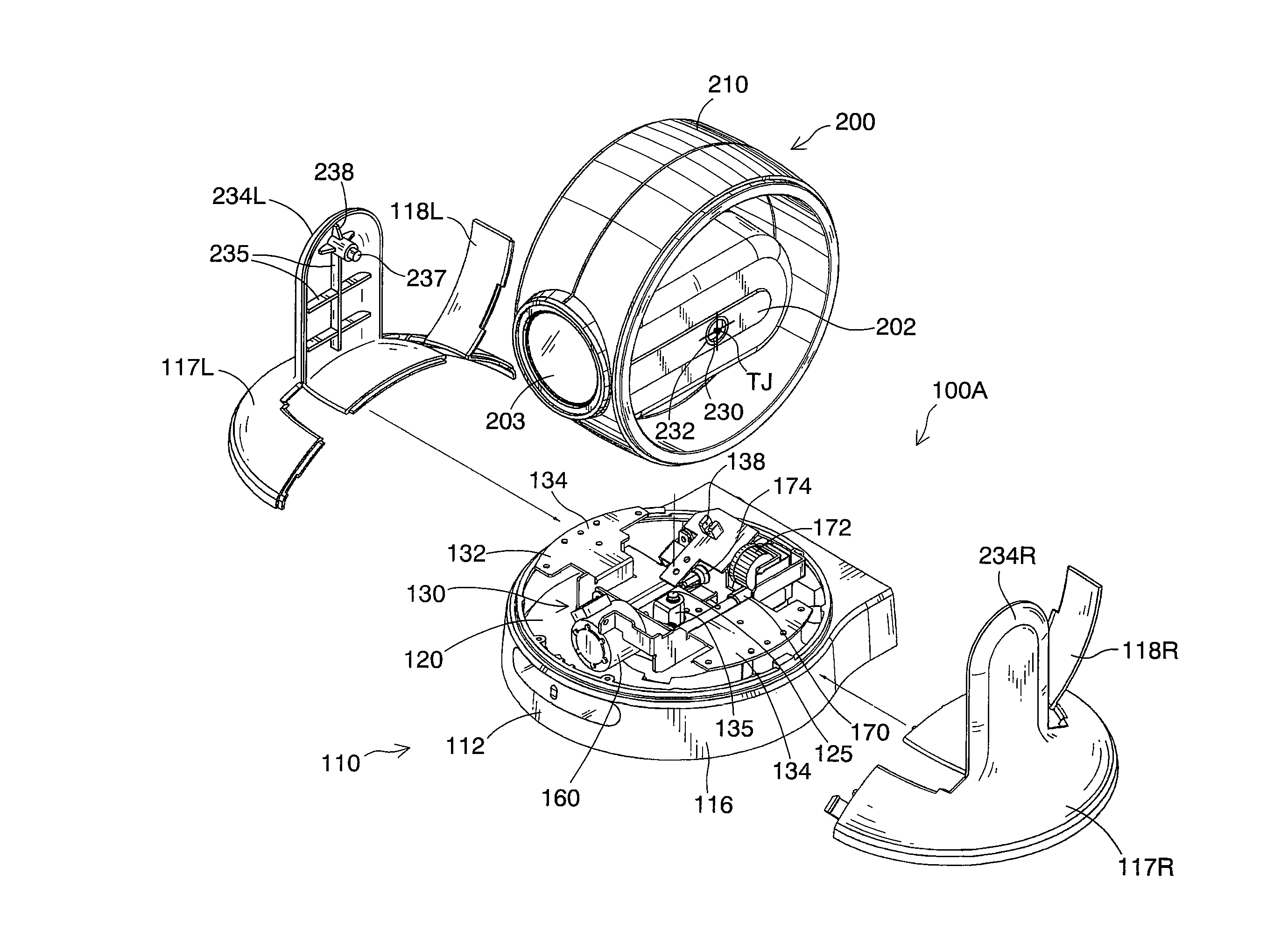
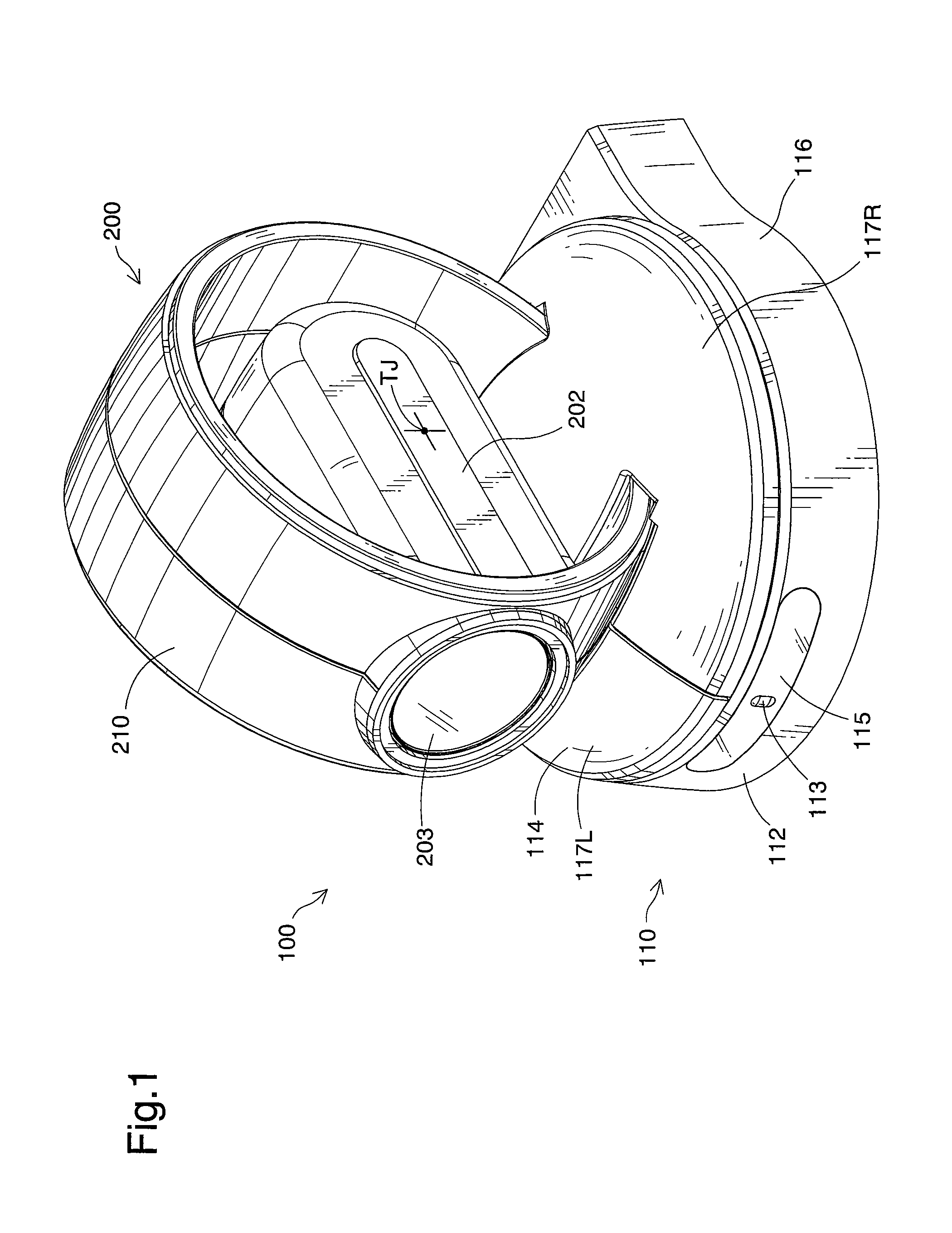
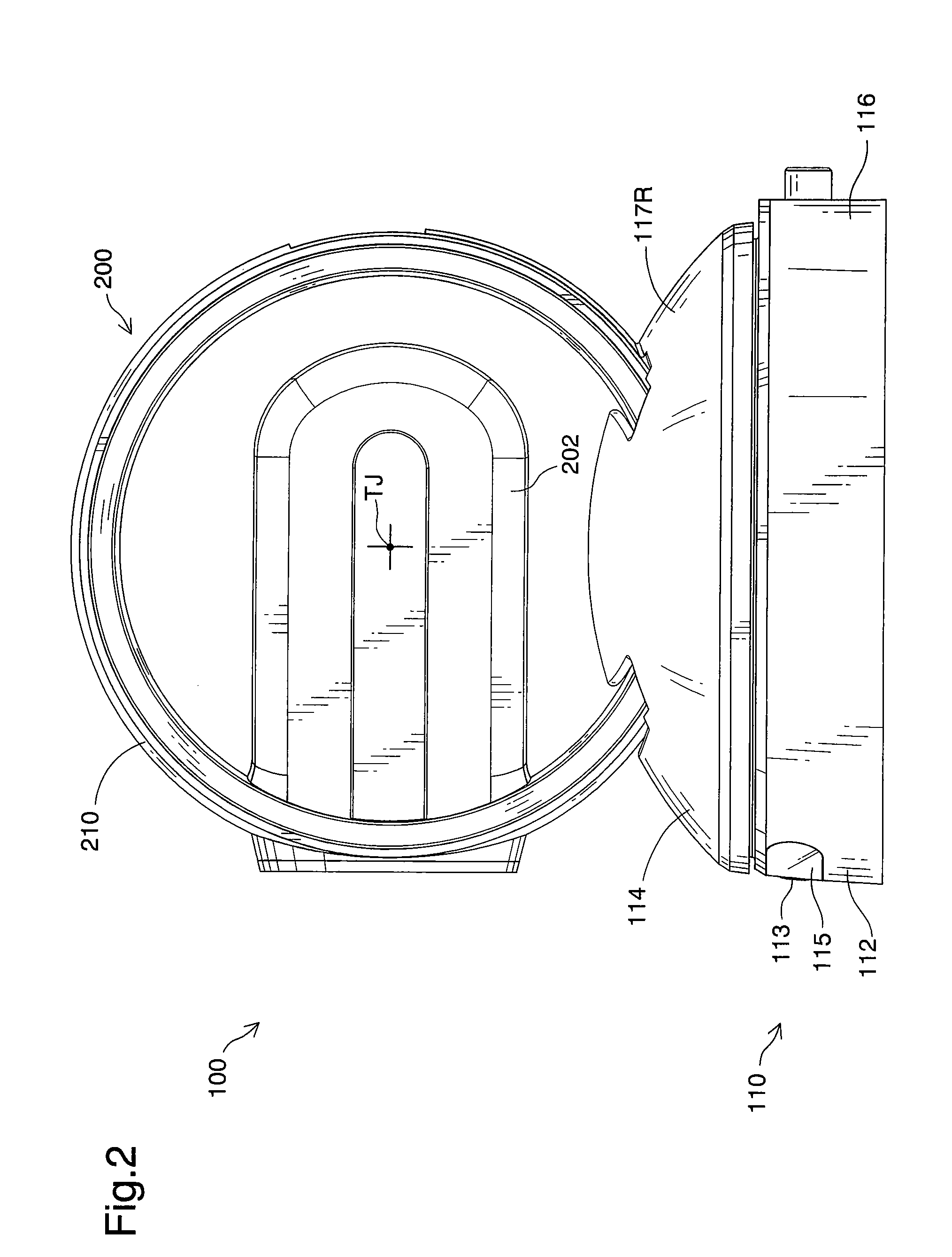
[0045]One mode of carrying out the invention is described below as a preferred embodiment with reference to the accompanied drawings. The description first regards the general overview and the operations of an imaging apparatus 100 as an application of a security camera in one embodiment of the invention. FIG. 1 is a perspective view showing an imaging apparatus 100 as application of a security camera in one embodiment of the invention. FIG. 2 is a side view showing the imaging apparatus 100 of the embodiment. FIG. 3 is a perspective view showing a camera assembly 200 of the imaging apparatus 100 tilted to an upper-most end in a vertical movable range. FIG. 4 is a perspective view showing the camera assembly 200 tilted to a lower-most end in the vertical movable range. FIG. 5 is a perspective view showing the camera assembly 200 panned to one further-most end in a horizontal movable range. FIG. 6 is a perspective view showing the camera assembly 200 panned to the other further-most ...


PUM


Abstract

In the imaging apparatus of the invention, a camera assembly 200 including a camera 202 is mounted on and supported by a base 110 in a pivotally rotatable manner in a vertical direction to allow tilting motions of the camera 202. First through fourth rollers 141 through 144 provided in an assembly fixation structure 114 of the base 110 support the camera assembly 200 to allow pivotal rotation of the camera assembly 200. The driving force of a tilting motor 160 built in a pedestal plate unit 130 of the assembly fixation structure 114 is transmitted to frame side faces of the camera assembly 200 via a tilting worm gear shaft 170 and a tilting rotation gear 172 to allow the tilting motions of the camera frame 200. This arrangement of the invention enables further downsizing of the whole imaging apparatus applied to, for example, a security camera.

Description

CROSS-REFERENCE TO RELATED APPLICATION[0001]The present application claims the priority based on Japanese Patent Application No. 2006-190179 filed on Jul. 11, 2006, the disclosure of which is hereby incorporated by reference in its entirety.BACKGROUND OF THE INVENTION[0002]1. Field of the Invention[0003]The present invention relates to an imaging apparatus equipped with a camera rotatable at least in a vertical direction.[0004]2. Description of the Related Art[0005]Imaging apparatuses have diversity of applications and are used, for example, as security cameras in various locations including banks, railway stations, supermarkets, convenience stores, and video game arcades. With the wide spread of the Internet, another prospective application of imaging apparatuses are web cameras for video image transfer.[0006]One prior art structure of a security camera device is designed to allow pivotal rotations of a camera both in a horizontal direction and in a vertical direction, with a view ...

Claims


Application Information

Patent Timeline
Patent Type & Authority Patents(United States)
IPC IPC(8): H04N5/225G03B17/00
CPCF16M11/10F16M11/12F16M11/18F16M11/2014H04N5/2251G03B37/02G08B13/19619G08B13/19632G03B17/56G03B17/561H04N23/50
Inventor YAMANE, AKIRASUGIYAMA, EIJI
Owner ELMO CO LTD
Why Eureka
Try Eureka