
Optical pickup, optical information recording device, optical information recording method, optical information reproduction device, optical information reproduction method and optical information recording medium

a technology of optical information and recording device, applied in the direction of optical recording/reproducing/erasing method, optical recording device, optical recording device, etc., can solve the problems of difficult to ensure the stable reading and recording of information, and achieve the reduction of the number of optical components related to such control processes, stable reading, and the effect of reducing the number of optical components

Inactive Publication Date: 2011-04-19
SONY CORP
View PDF10 Cites 2 Cited by
  • Summary
  • Abstract
  • Description
  • Claims
  • Application Information

AI Technical Summary

Benefits of technology

The present invention provides an optical pickup, optical information recording device, optical information recording medium, and optical information reproduction device that can focus two beams to a point on the recording medium without requiring advanced control systems. This simplifies the structure of the device and reduces the complexity of the control processes. The invention also eliminates the need for two optical paths for two beams, reducing the number of optical components. Additionally, the invention uses a recording layer that forms a recording mark on the recording medium through a photoreaction, and a reflection layer that at least partly reflects a servo beam for positioning the recording beam. This further simplifies the device and reduces the complexity of the control processes.

Problems solved by technology

If it employs such an advanced control system, the structure becomes complicated and thereby makes it difficult to ensure the stable reading and recording of information.

Method used


Image

  • Optical pickup, optical information recording device, optical information recording method, optical information reproduction device, optical information reproduction method and optical information recording medium
  • Optical pickup, optical information recording device, optical information recording method, optical information reproduction device, optical information reproduction method and optical information recording medium
  • Optical pickup, optical information recording device, optical information recording method, optical information reproduction device, optical information reproduction method and optical information recording medium

Examples


Embodiment Construction

[0036]An embodiment of the present invention will be described in detail with reference to the accompanying drawings.

(1) Configuration of Optical Disc

(1-1) Layer Structure of Optical Disc

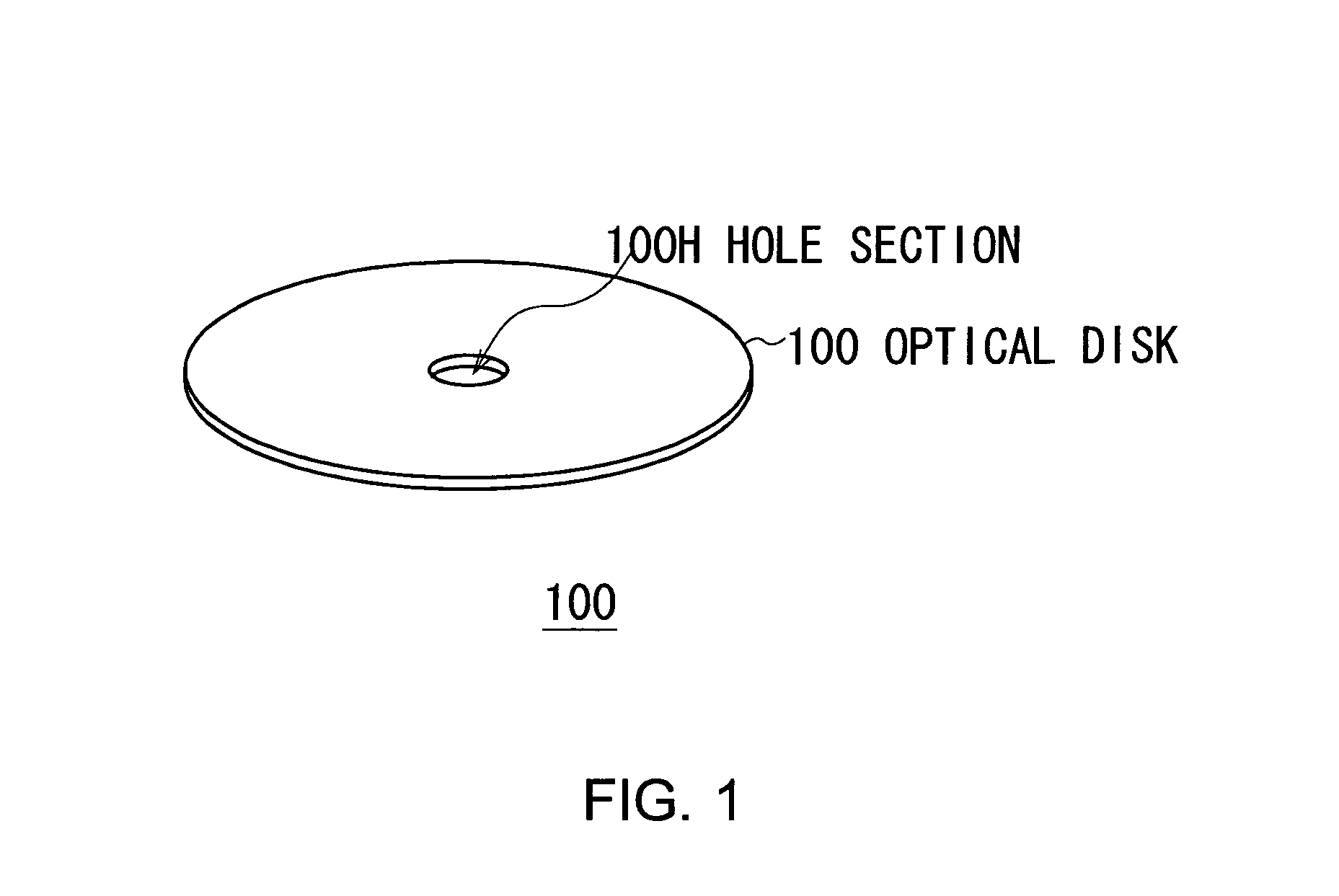
[0037]The following describes an optical disc 100, which is used as an optical information recording medium in this embodiment of the present invention. FIG. 1 is an appearance diagram. The optical disc 100 is a disc-shaped disc with a diameter of approximately 120 mm, similar to CD, DVD and BD. A hole section 100H is formed at the center of the optical disc 100.

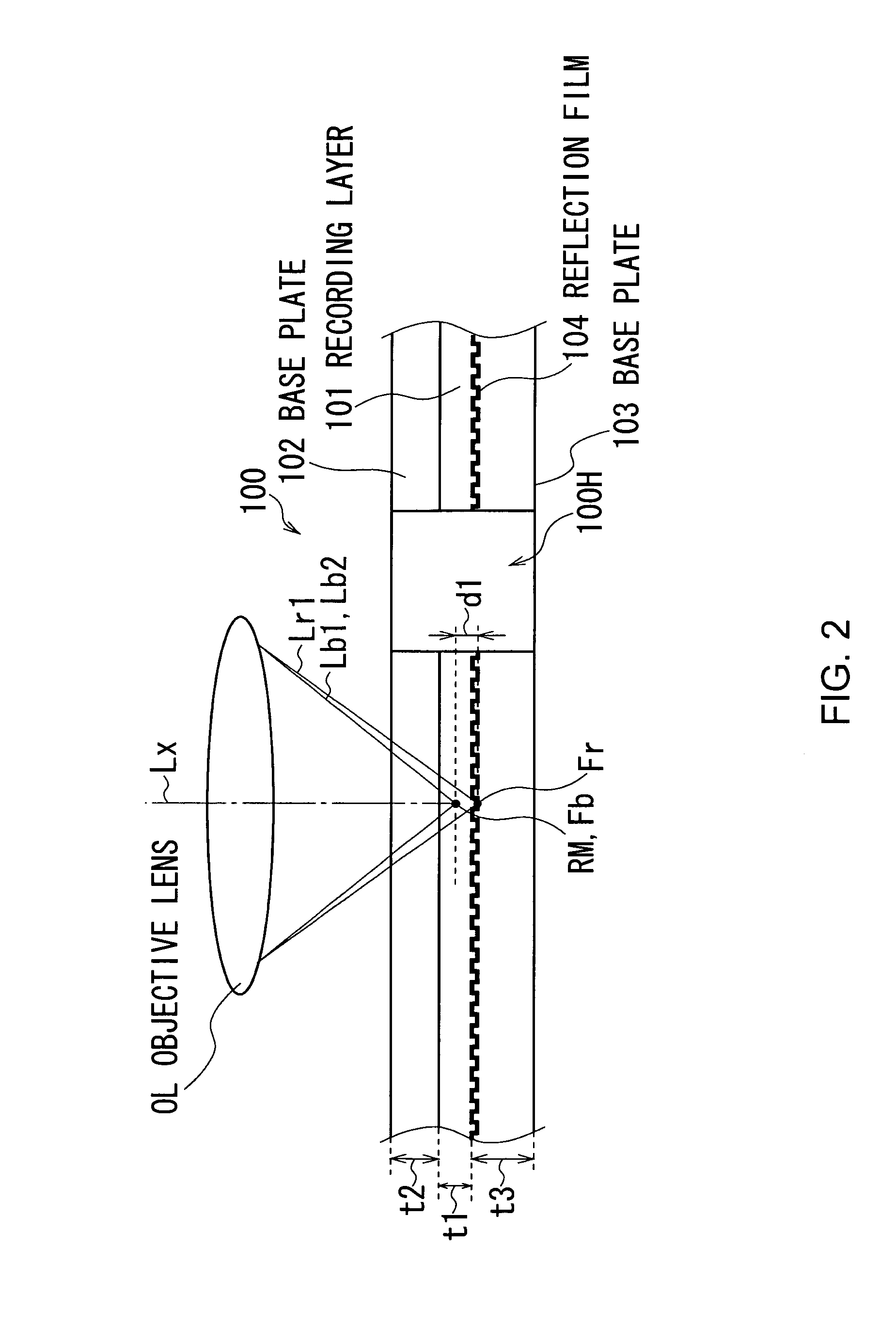
[0038]FIG. 2 is a cross-section diagram. The optical disc 100 includes a recording layer 101 in the middle of the disc 100. The recording layer 101 on which information is recorded is sandwiched between base plates 102 and 103.

[0039]Incidentally, the thickness t1 of the recording layer 101 is about 0.3 mm. The thickness t2 and t3 of the base plates 102 and 103 are the same, around 0.6 mm.

[0040]The base plates 102 and 103 are made from materi...


PUM

PropertyMeasurementUnit
diameteraaaaaaaaaa
thickness t2aaaaaaaaaa
wavelengthaaaaaaaaaa

Abstract

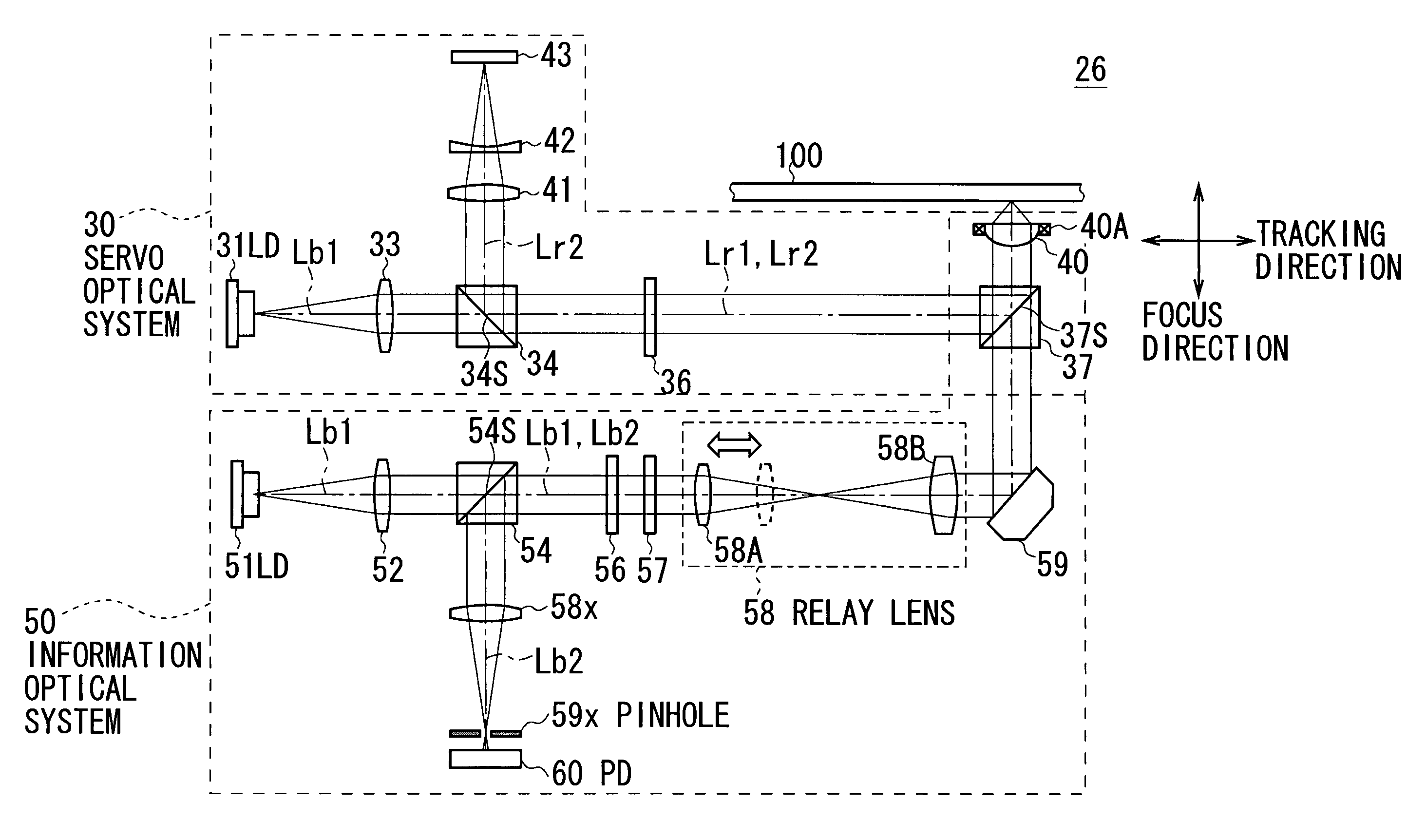
An optical pickup includes: an objective lens that collects a first beam and a second beam and emits the first and second beam toward an optical information recording medium on which information can be recorded as a recording mark as a result of being exposed to the first beam; a section that drives the objective lens to focus the second beam on a reflection layer formed on the optical information recording medium, the reflection layer at least partly reflecting the second beam; and a section that changes the convergence state of the first beam to position a focal point of the first beam a distance away from a focal point of the second beam in the direction of depth in order to place the focal point of the first beam at a target depth.

Description

CROSS REFERENCES TO RELATED APPLICATIONS[0001]The present invention contains subject matter related to Japanese Patent Application JP2007-168992 filed in the Japanese Patent Office on Jun. 27, 2007, the entire contents of which being incorporated herein by reference.BACKGROUND OF THE INVENTION[0002]1. Field of the Invention[0003]The present invention relates to an optical pickup, optical information recording device, optical information recording method, optical information reproduction device, optical information reproduction method and optical information recording medium, and is preferably applied to an optical information recording and reproducing device that records information on a recording medium by using an optical beam and reproduces the information from the recording medium by using an optical beam, for example.[0004]2. Description of the Related Art[0005]As an optical information recording and reproducing device, an optical disc device is popular: The optical disc device...

Claims


Application Information

Patent Timeline
Patent Type & Authority Patents(United States)
IPC IPC(8): G11B7/00
CPCG11B7/08511G11B7/1275G11B7/1378G11B7/1381G03H2001/2615G03H2250/32G03H2250/42G11B7/0065G11B2007/0013G11B7/26G11B7/0938G11B7/09G11B7/1372G11B7/258
Inventor MIYAMOTO, HIROTAKAYUAN, JINGCHENG
Owner SONY CORP
Learn More