Motor-driven steering assist apparatus

a technology of assist apparatus and motor drive, which is applied in mechanical apparatus, transportation and packaging, and can solve the problems of difficult to avoid interference with peripheral equipment, complicated consideration, and complicated procedures, and achieves the effects of improving the attaching property, compact size and weight saving

Inactive Publication Date: 2011-04-26
HITACHI ASTEMO LTD
View PDF9 Cites 6 Cited by
  • Summary
  • Abstract
  • Description
  • Claims
  • Application Information

AI Technical Summary

Benefits of technology

[0008]An object of the present invention is to improve an attaching property to a vehicle body and to achieve a compact size and weight saving, in a motor-driven steering assist apparatus.

Problems solved by technology

The attaching boss provided in the outer periphery of the second housing protrudes more to an outer side, the vehicle body side bracket is enlarged in size, and it is hard to avoid an interference with peripheral equipment such as an engine or the like.
Further, the second housing receives the worm gear and forms a different outer shape, and complicated consideration is necessary for arranging the attaching boss while avoiding the worm gear receiving portion.
Three attaching bolts inserted and attached to the attaching boss are fastened, so that it is necessary to carry out a complicated procedure.

Method used


Image

  • Motor-driven steering assist apparatus
  • Motor-driven steering assist apparatus
  • Motor-driven steering assist apparatus

Examples


embodiment 1

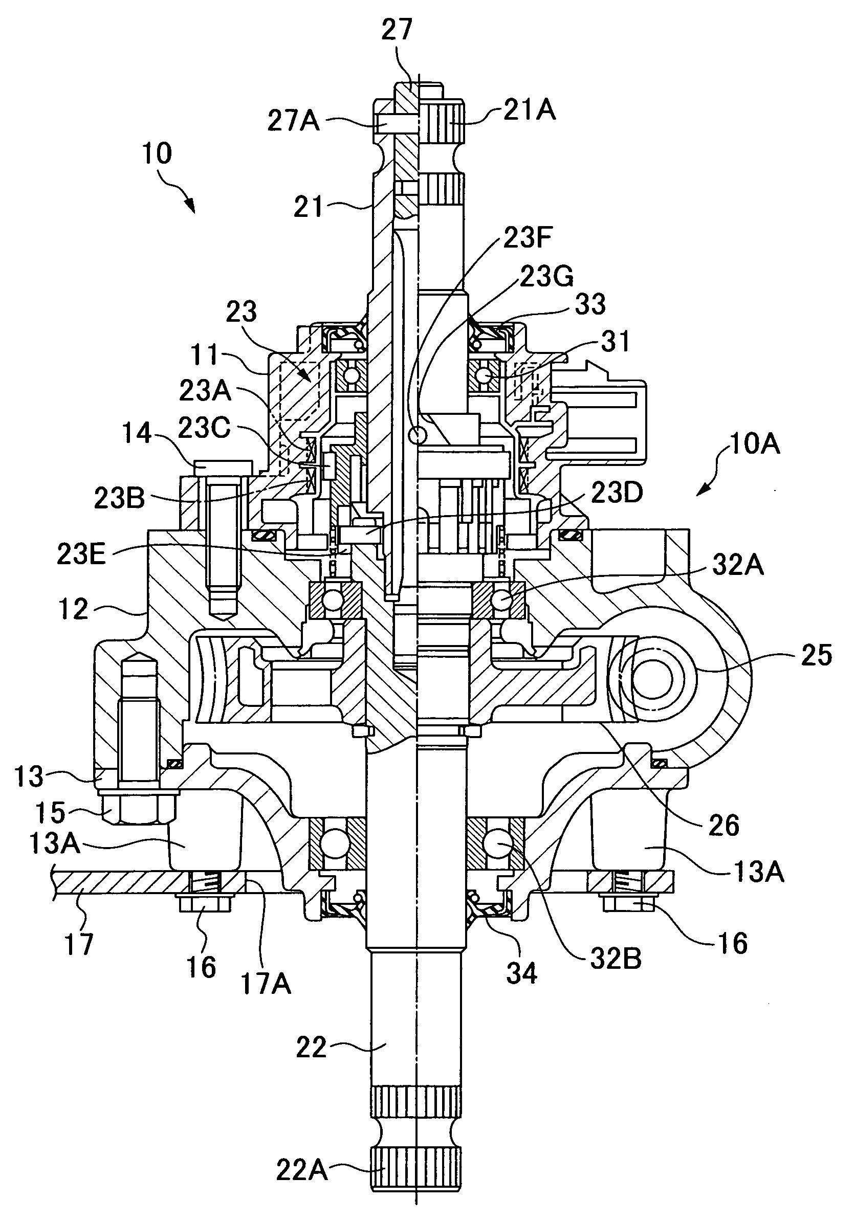
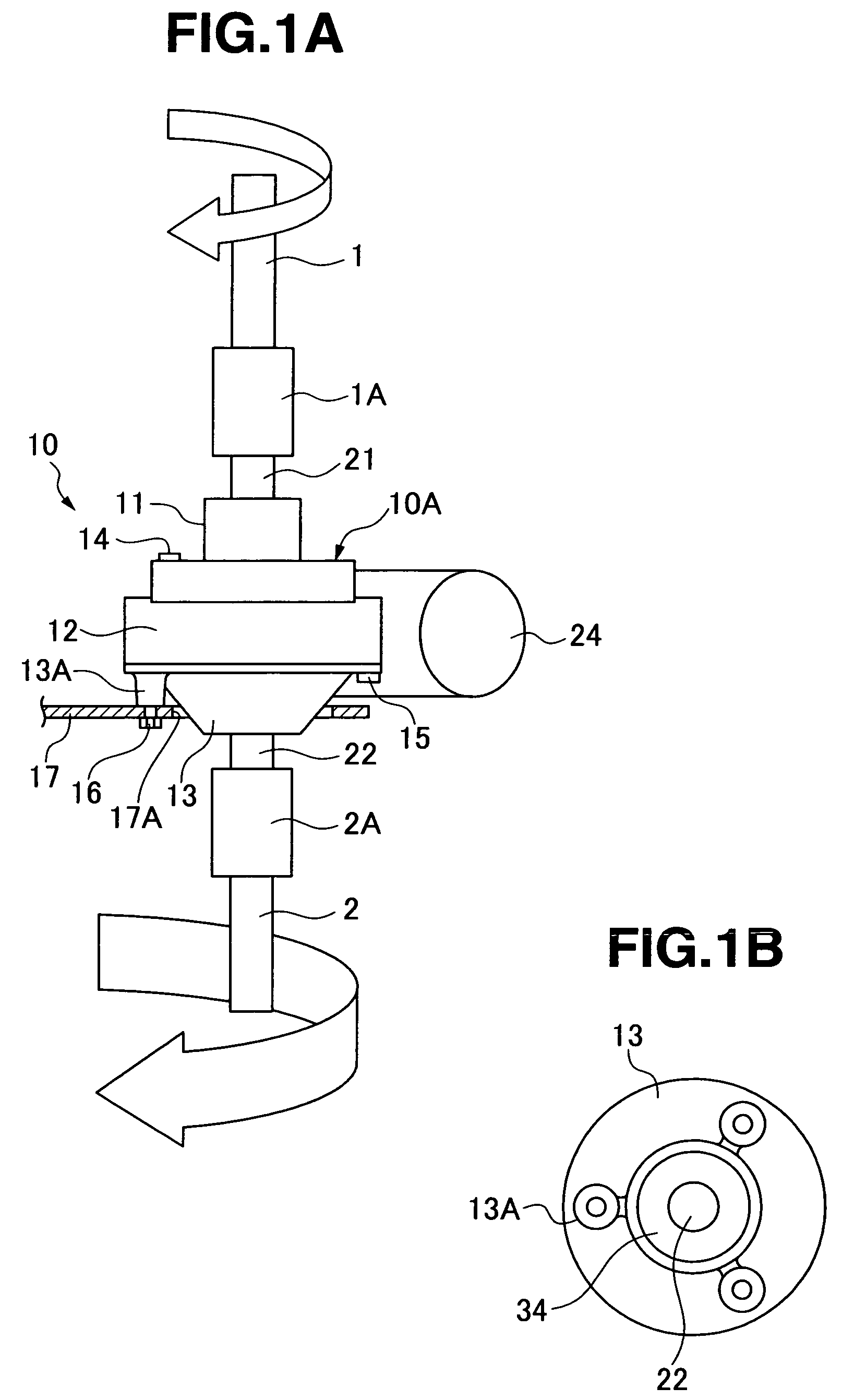
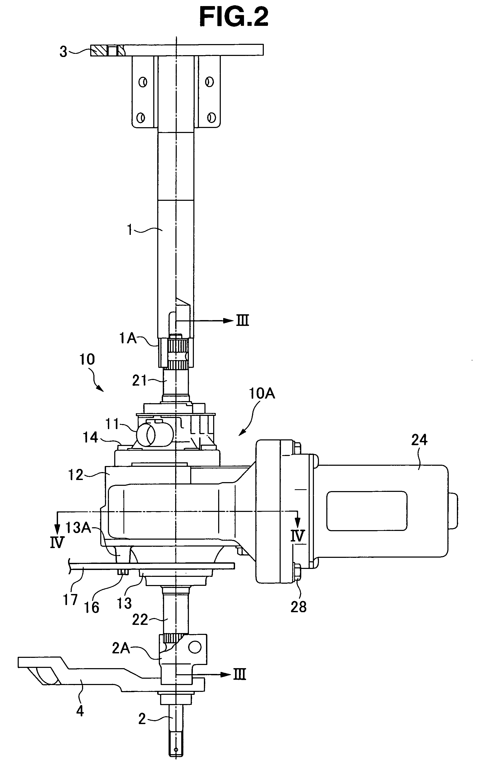
[0023]A motor-driven steering assist apparatus 10 may be applied to a rough road traveling vehicle, for example, a buggy vehicle, a snowmobile and the like. The apparatus is interposed between a steering wheel side steering member 1 and a tire wheel side steering member 2, as shown in FIGS. 1 and 2, and assists steering force applied to the steering wheel by a driver, on the basis of a generated torque of an electric motor 24. A steering wheel attaching member 3 is fixed to the steering wheel side steering member 1, and a pitman arm 4 is fixed to the wheel side steering member 2. The pitman arm 4 is coupled to a front wheel via right and left tie rods.

[0024]The motor-driven steering assist apparatus 10 comprises a single unit body 10A covered by first housing 11 (upper housing or upper cover), second housing (main housing), and third housing (lower housing or lower cover) 13, as shown in FIGS. 1 to 4. The unit body 10A has an input shaft 21, an output shaft 22, a torque sensor 23, a...

embodiment 2

[0041]A motor-driven steering assist apparatus 110 may be applied to a rough road traveling vehicle, for example, a buggy vehicle, a snowmobile and the like. The apparatus is interposed between a steering wheel side steering member 101 and a tire wheel side steering member 102, as shown in FIGS. 5 and 6, and assists steering force applied to the steering wheel by a driver, on the basis of generated torque of an electric motor 124. A steering wheel attaching member 103 is fixed to the steering wheel side steering member 101, and a pitman arm 104 is fixed to the wheel side steering member 102. The pitman arm 104 is coupled to a front wheel via right and left tie rods.

[0042]The motor-driven steering assist apparatus 110 has a single unit body 110A covered by first housing 111 (upper housing or upper cover), second housing (main housing), and third housing (lower housing or lower cover) 113, as shown in FIGS. 5 to 8. The unit body 110A has an input shaft 121, an output shaft 122, a torq...


PUM


Abstract

In a motor-driven steering assist apparatus, a gear train transmitting a rotation of an electric motor to an output shaft comprises a single unit body surrounded by housings, and an attaching boss to a vehicle body side bracket is provided in a lower surface of the housing as seen from an axial direction of the output shaft.

Description

BACKGROUND OF THE INVENTION[0001]1. Field of the Invention[0002]The present invention relates to a motor-driven steering assist apparatus.[0003]2. Description of the Related Art[0004]In a motor-driven steering assist apparatus of a rough road traveling vehicle, such as a buggy vehicle or the like, as described in Japanese Patent Application Laid-open No. 2004-336565 (patent document 1), there is a structure which is interposed between a steering wheel and a tire wheel side steering member, which assists steering force applied to the steering wheel by a driver on the basis of torque generated by an electric motor.[0005]In the motor-driven steering assist apparatus in the patent document 1, a single unit body covered by first to third housings has an input shaft to which a steering wheel is connected and an output shaft to which a wheel side steering member is connected. A torque sensor is provided between the input shaft and the output shaft. An electric motor is driven in correspond...

Claims


Application Information

Patent Timeline
Patent Type & Authority Patents(United States)
IPC IPC(8): F16H35/00
CPCB62D1/16B62D5/0409Y10T74/2186
Inventor SAITO, MITSUOHATA, KOICHI
Owner HITACHI ASTEMO LTD
Why Eureka
Try Eureka