Deconfinement device for the casing of a piece of an ammunition

a technology of deconfinement device and ammunition, which is applied in the direction of ammunition fuze, ammunition storage, weapons, etc., can solve the problems of projectile detonation, only being able to implement deconfinement means, and generating gases during breakdown. , to achieve the effect of reducing the thickness

Active Publication Date: 2011-04-26
NEXTER MUNITIONS
View PDF12 Cites 7 Cited by
  • Summary
  • Abstract
  • Description
  • Claims
  • Application Information

AI Technical Summary

Benefits of technology

The base may incorporate at least one circular channel ensuring a reduction in its thickness.

Problems solved by technology

When an explosive load is overheated, its breakdown generates gases which are trapped inside the projectile casing.
The pressure builds up strongly and causes the projectile to detonate.
However, such deconfinement means may only be implemented during a storage phase of the projectile, phase during which the fuse is dismounted.
In this case, overheating can lead both to the ignition of the load itself further to a build-up in the pressure, and to the ignition of the fuse thereby also causing the explosive load to detonate.
Although it is interesting, this device is, however, insufficiently effective since the total surface area of the vents is too small and does not enable a rapid deconfinement of the inside of the projectile body.
Such a device is complicated in that it implements a spring held in a compressed state.
The mechanical strength of the fusible material is, furthermore, not ensured, namely after long period of storage, thereby endangering the reliability of this device.
However, such a projectile does not incorporate an explosive load.
With such a projectile, the problem of the protection of a load against increasing temperatures is not raised.
Furthermore, the structure described is not adapted to the ignition of an explosive load.

Method used


Image

  • Deconfinement device for the casing of a piece of an ammunition
  • Deconfinement device for the casing of a piece of an ammunition
  • Deconfinement device for the casing of a piece of an ammunition

Examples


Embodiment Construction

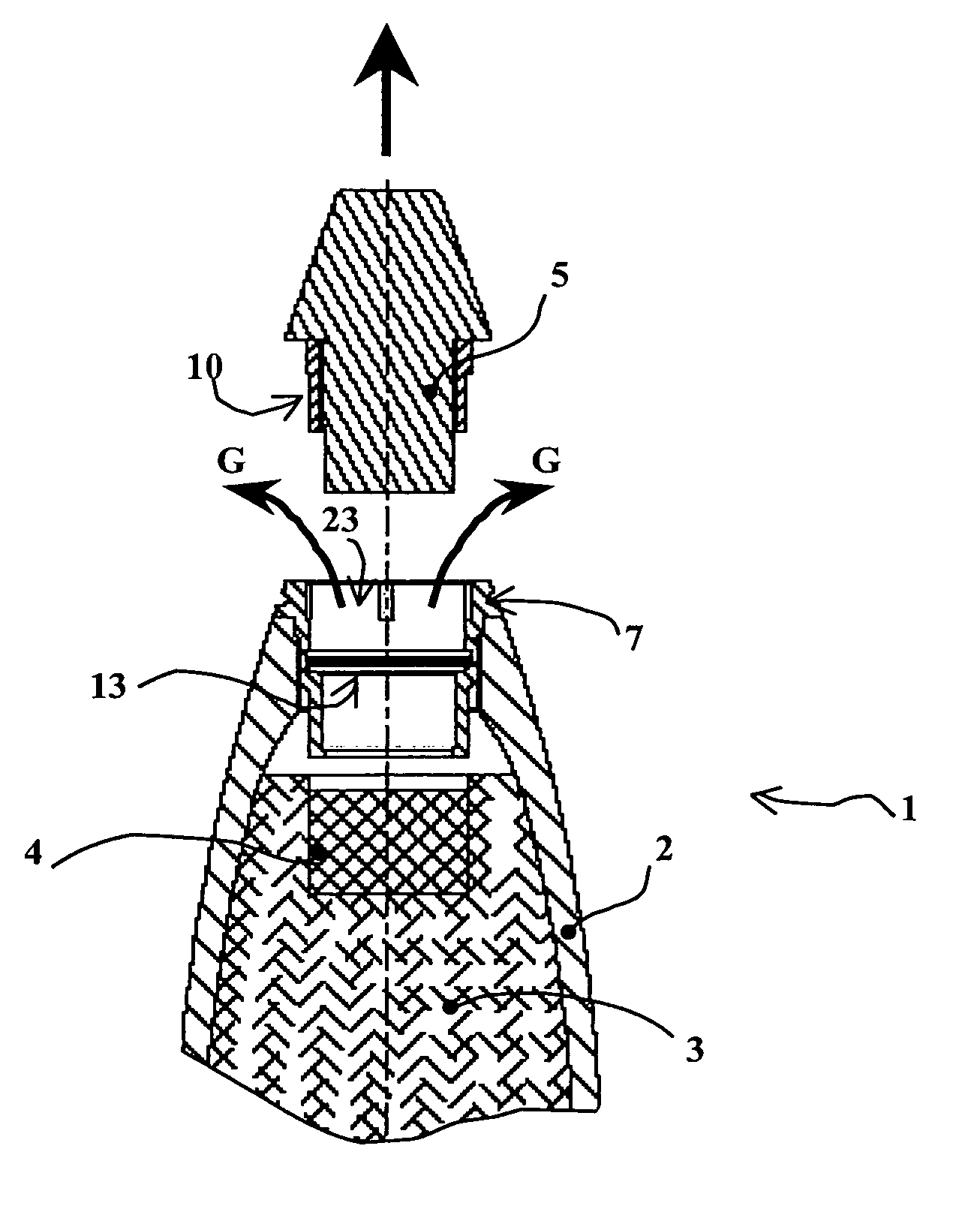
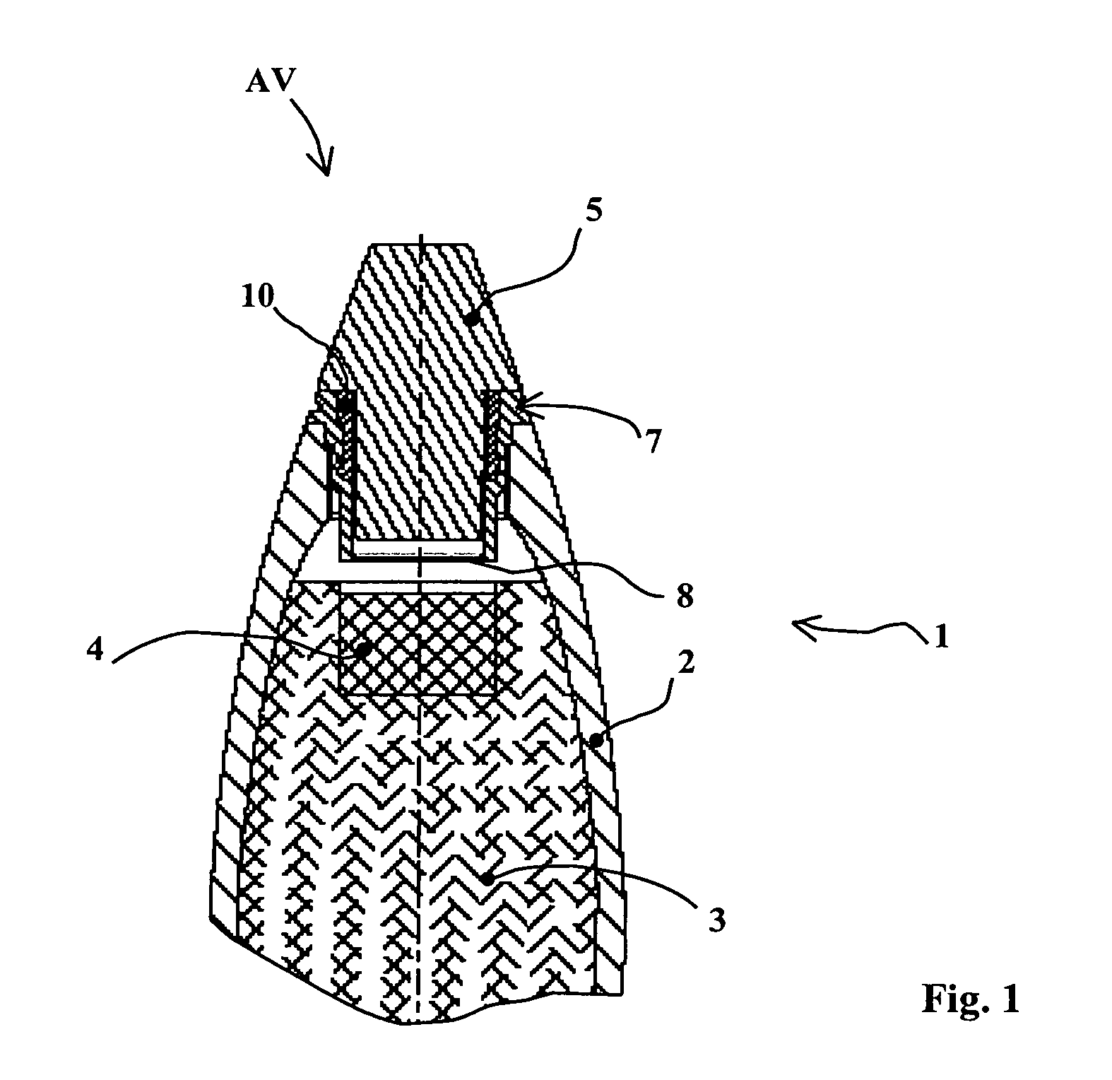
FIG. 1 shows a partial longitudinal section of the front part of a piece of ammunition 1 that is an artillery projectile. This projectile is shown schematically here. It incorporates a casing or body 2 enclosing an explosive load 3. Its front part AV carries a fuse 5.

The explosive load 3 has on its surface a pellet 4 of a priming explosive composition.

A connecting ring 7 is linked to the body 2 of the projectile by threading. This connecting ring incorporates a base 8 forming a plate that may be projected onto the explosive load 3, 4 when the fuse is ignited 5.

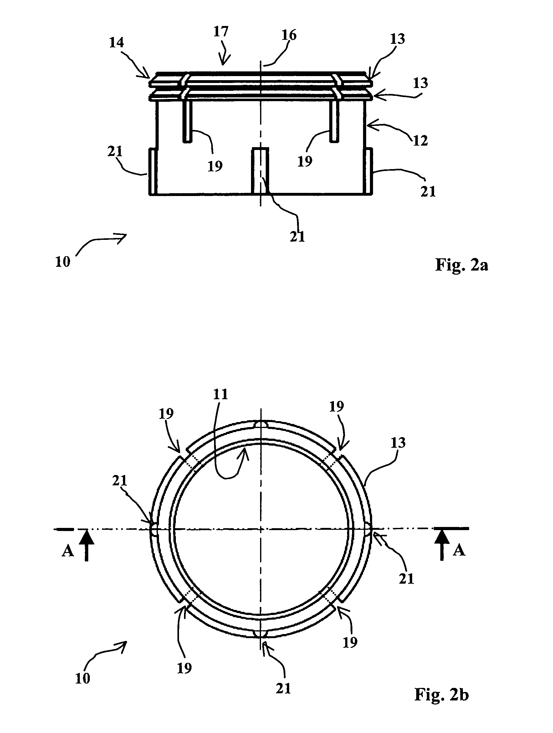
The base 8 will advantageously incorporate at least one circular channel 9 (see FIG. 3b) which ensures a reduction in its thickness. This channel is obtained by machining one face of the base. It thus forms a zone of reduced thickness for the base 8.

The ring 7 is made of steel. The thickness of the connecting ring at the base 8 is of around 1 mm.

Igniting the fuse 5 causes the base 8 to be cut out at the channel 9.

This results ...


PUM


Abstract

A deconfinement device for the casing of a piece of ammunition enclosing an explosive load able to be ignited by a priming fuse, said device comprising a connecting ring linked to the casing and enabling the priming fuse to be joined to said casing, wherein said device incorporates a structure to ensure a weakened and shearable link between said fuse and said connecting ring, said link being sheared further to an increase in the pressure inside said casing, said connecting ring incorporating a base forming a plate that can be projected onto said explosive load during the ignition of said fuse, said base being able to be fractured by the presence of pressure inside said body of said projectile.

Description

BACKGROUND OF THE INVENTION1. Field of the InventionThe technical scope of the invention is that of devices to ensure the deconfinement of an ammunition casing enclosing an explosive load and more particularly deconfinement devices for an explosive projectile body, whatever the caliber or type of weapon firing this projectile.2. Description of the Related ArtDeconfinement devices enable the detonation of a projectile to be avoided further to overheating, for example during a fire.When an explosive load is overheated, its breakdown generates gases which are trapped inside the projectile casing.The pressure builds up strongly and causes the projectile to detonate.It is known to provide deconfinement devices which enable such gases to be evacuated out of the projectile so as to avoid this build-up in pressure eventually leading to detonation.Patent DE2131748 thus describes a closing plug for a projectile body which is put into position when the projectile is being stored. This plug inc...

Claims


Application Information

Patent Timeline
Patent Type & Authority Patents(United States)
IPC IPC(8): F42B3/18
CPCF42C19/02F42B39/20
Inventor COTET, STEPHANEDESGLAND, LAURENTDION, DOMINIQUE
Owner NEXTER MUNITIONS
Why Eureka
Try Eureka