Fuel-injection device

a technology of fuel injection and fuel injection chamber, which is applied in the direction of liquid fuel feeders, fuel injecting pumps, machines/engines, etc., can solve the problems of unfavorable sound radiation and adverse effects, and achieve the effects of reducing noise development, improving sealing, and reducing the generation of dynamic alternating forces

Inactive Publication Date: 2011-04-26
ROBERT BOSCH GMBH
View PDF23 Cites 7 Cited by
  • Summary
  • Abstract
  • Description
  • Claims
  • Application Information

AI Technical Summary

Benefits of technology

[0005]The fuel-injection device according to the present invention having the characterizing features described herein has the advantage of providing improved sealing by simple measures implemented on the fuel injector and the pipe connection of the fuel-distributor line, and of achieving reduced noise development. According to the exemplary embodiments and / or exemplary methods of the present invention, the dynamic pressure variations in the fuel during the opening and closing of the fuel injector are mostly kept away from the pipe connection by routing them through the pipe connection directly into the fuel-distributor line without triggering dynamic pressure fluctuations in the volume of the pipe connection. A pressure-wave guide, which ensures that the generation of dynamic alternating forces is reduced considerably, is used for this purpose. The result is reduced wear of the sealing rings of the fuel injector and a markedly reduced noise generation. The slowly variable buildup and reduction of pressure is retained since in high loading states the force produced by the pressure further supplements the holding down of the fuel injectors via holding-down clamps with respect to the combustion pressure of the combustion chamber.
[0007]If the pressure-wave guide is affixed on the fuel injector, it is especially advantageous if the mounting is implemented on a fuel filter or on a connection sleeve of the fuel injector, especially by an extended plastic extrusion coating or with the aid of a catch, snap-in or clip connection.
[0010]An annular leakage gap is formed in the region of the discharge opening of the fuel-distributor line or the flow opening of the pipe connection. Additional advantageous specific embodiments of the leakage gap may be realized by contouring the surface of the pressure-wave guide. The leakage gap between the pressure-wave guide and the wall surrounding it permits a slow buildup and reduction in pressure in the pipe connection according to the system pressure, i.e., a static pressure compensation.

Problems solved by technology

During operation, hydraulic forces that are proportional to the cross-sectional area are generated with respect to the fuel injector and the fuel-distributor line; these can harm the sealing ring and are transmittable to the engine structure in the form of structure-borne noise and thereby lead to undesired sound radiation (FIG. 1).
These solutions can also have the previously mentioned adverse effects.

Method used


Image

  • Fuel-injection device
  • Fuel-injection device
  • Fuel-injection device

Examples


first embodiment

[0032]Various approaches according to the exemplary embodiments and / or exemplary methods of the present invention are conceivable to produce the line connection between fuel injector 1 and the volume of fuel rail 4 with the aid of pressure-wave guide 20. FIG. 5 schematically illustrates a pressure-wave guide 20 according to the present invention. In this exemplary embodiment, pressure-wave guide 20 is made of, for example, a media-resistant plastic (polyamide) and is mounted on a fuel filter 22 of fuel injector 1 by pressing in or clipping. It is also conceivable to form pressure-wave guide 20 in one piece on the plastic base element of fuel filter 22.

second embodiment

[0033]FIG. 6 schematically illustrates a pressure-wave guide 20 according to the present invention. In this specific embodiment pressure-wave guide 20 is made of metal, for example, and pressure-wave guide 20 is affixed on, e.g., a connection sleeve 23 of fuel injector 1 by a flange 24 that extends radially in an outward direction, using bonding, welding, soldering, etc. Here, too, an integral design is conceivable, in which pressure-wave guide 20 emerges directly from a deep-drawn or turned connection sleeve 23. The exemplary embodiments shown in FIGS. 5 and 6 have no permanent connection of pressure-wave guide 20 to fuel rail 4. Instead, a clearance fit is provided to produce leakage gap 21. However, if a press fit is realized, then channel- or groove-type or screw-type depressions may be formed on the outer circumference of pressure-wave guide 20.

third embodiment

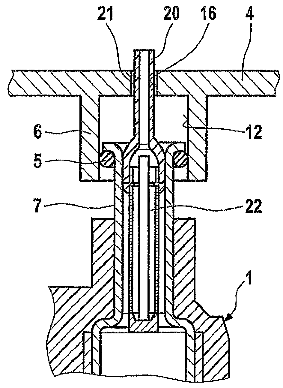
[0034]FIG. 7 shows a pressure-wave guide 20 according to the present invention, in which pressure-wave guide 20 is fixed in place on fuel rail 4 and freely projects into fuel injector 1, e.g., into fuel filter 22. Pressure-wave guide 20 is mounted on fuel rail 4 with the aid of, e.g., a catch, snap-in, clip connection or similar device. The permanent connection is implemented in such a way that a leakage gap 21 remains. As an alternative or in addition, a second leakage gap 21′ may be provided as well, i.e., between pressure-wave guide 20 and fuel filter 22 or some other component of fuel injector 1 surrounding pressure-wave guide 20. FIGS. 8 and 9 show cross-sections through pressure-wave guide 20 in the region of leakage gap 21′; it can be seen that the outer surface of pressure-wave guide 20 is contoured. For example, the outer surface of pressure-wave guide 20 may have longitudinal ribs 24 (FIG. 8) or longitudinal channels or grooves 25 (FIG. 9).


PUM


Abstract

The fuel-injection device is characterized by an especially low-noise design. The fuel-injection device includes at least one fuel injector and a fuel rail having at least one pipe connection, the fuel injector being introduced into a receiving bore of the pipe connection, and the fuel rail having a discharge opening to supply fuel to the fuel injector. Provided between the fuel injector and the fuel rail is a pressure-wave guide connecting both, in such a way such that dynamic pressure fluctuations in the fuel injector are able to be routed largely past the volume of the receiving bore of the pipe connection. The fuel-injection device is especially suitable for the direct injection of fuel into a combustion chamber of a mixture-compressing internal combustion engine having external ignition, but it is also suitable for the injection of fuel into an intake manifold.

Description

FIELD OF THE INVENTION[0001]The present invention is based on a fuel-injection device of the type set forth herein.BACKGROUND INFORMATION[0002]A fuel-injection device is discussed in DE 10 2004 048 401 A1. The fuel-injection device includes a plurality of fuel injectors, a receiving bore in the cylinder head for each fuel injector, and an individual pipe connection of a fuel-distributor line used to supply fuel to the fuel injectors. The fuel injector is inserted into the relative solid pipe connection of the fuel-distributor line and sealed with the aid of a sealing ring. The pipe connection emerges from the actual fuel-distributor line in one piece. The fuel-distributor line is permanently connected to the cylinder head, e.g., by a screw-type connection. A U-shaped holding-down clamp is clamped between the pipe connection of the fuel-distributor line and the fuel injector.[0003]The holding-down clamp includes a base element in the form of a partial ring, from which an axially flex...

Claims


Application Information

Patent Timeline
Patent Type & Authority Patents(United States)
IPC IPC(8): F02M61/00
CPCF02M55/02F02M55/04F02M61/165F02M69/465F02M61/14F02M2200/315F02M2200/853
Inventor FISCHER, MICHAELFISCHER, ULRICHLANG, PETER
Owner ROBERT BOSCH GMBH
Why Eureka
Try Eureka