Rapid take up and vibration proof adjuster mechanism

a technology of adjuster mechanism and slack adjustment, which is applied in the direction of slack adjusters, friction linings, mechanical devices, etc., can solve the problems of increasing gap between the brake pad and the brake disc, increasing slack when the brake is applied, and reducing the effectiveness of the brake. , to prevent undesirable slack adjustment in the brake system

Inactive Publication Date: 2011-04-26
ARVINMERITOR TECH
View PDF13 Cites 6 Cited by
  • Summary
  • Abstract
  • Description
  • Claims
  • Application Information

AI Technical Summary

Benefits of technology

[0003]As brake pads or a brake disc wear a gap between the brake pads and brake disc increases. Due to the increase in the gap between the brake pads and the brake disc a brake actuator must travel farther to engage the brake. In other words, there is more slack when the brake is applied, which causes the brakes to become less effective. In order to compensate for slack, a slack adjustment mechanism moves the brake pads closer to the brake disc prior to brake engagement. This adjustment assures a consistent amount of actuator travel in spite of brake pad wear.
[0004]Conventional brake adjuster mechanisms use relatively complex mechanical assemblies to perform this function. Force from the brake actuator is commonly utilized to drive the adjuster mechanism, which may reduce brake effectiveness and efficiency.
[0005]In addition, the adjuster mechanism may shift while the brake is not being applied. Shifting may cause undesirable brake pad wear, or further increase slack in the brake system, which may reduce the brake performance.
[0008]The locking mechanism selectively engages an adjustment gear, or any rotational member engaged with the gear, to prevent the gear from being rotated and undesirably adjusting the gap between the brake pad and the brake disc. The locking mechanism prevents adjustment when the brake is not applied. The locking mechanism includes a latch interfitting with the gear to prevent rotation when engaged with the gear. The latch disengages from the gear after a predetermined amount of movement of the latch. Release of the locking mechanism allows the gear to rotate. The biasing member is mounted to engage and rotate the gear when the locking member is not preventing movement. The biasing member is of a type which applies a rotational force independent of the amount of pressure applied by the brake actuator. The biasing member may be a spring, electric motor, air powered motor or the like.
[0009]The present invention therefore provides a method of automatically adjusting slack independent of the pressure applied to the brake system. In addition, a locking device prevents undesirable adjustment of slack in the brake system.

Problems solved by technology

As brake pads or a brake disc wear a gap between the brake pads and brake disc increases.
In other words, there is more slack when the brake is applied, which causes the brakes to become less effective.
Conventional brake adjuster mechanisms use relatively complex mechanical assemblies to perform this function.
Force from the brake actuator is commonly utilized to drive the adjuster mechanism, which may reduce brake effectiveness and efficiency.
Shifting may cause undesirable brake pad wear, or further increase slack in the brake system, which may reduce the brake performance.

Method used


Image

  • Rapid take up and vibration proof adjuster mechanism
  • Rapid take up and vibration proof adjuster mechanism
  • Rapid take up and vibration proof adjuster mechanism

Examples


Embodiment Construction

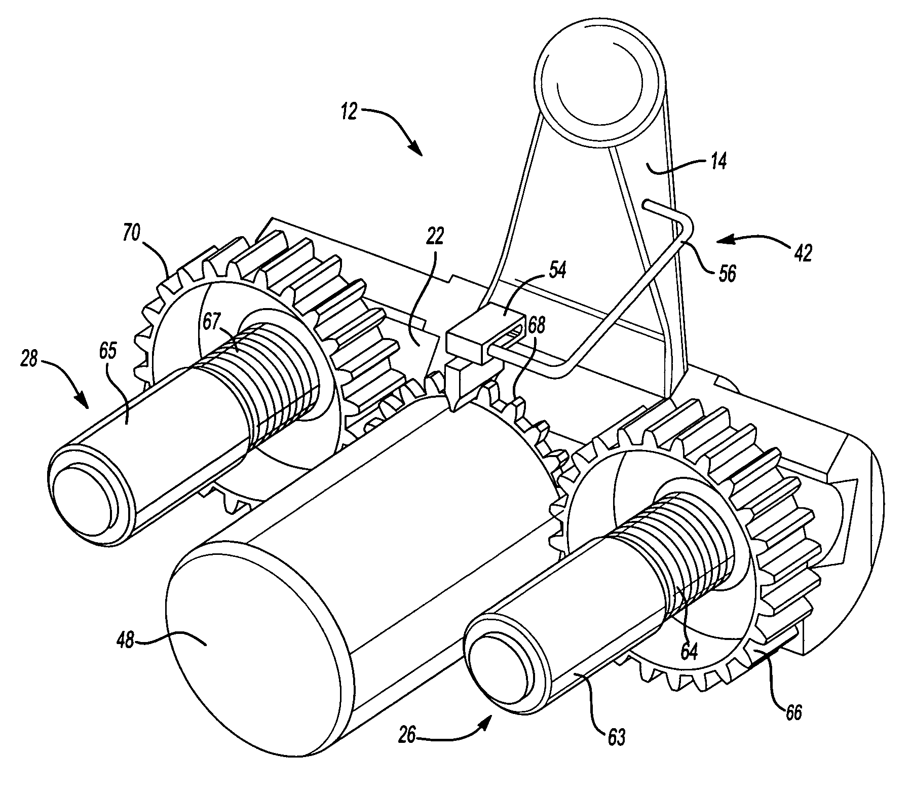
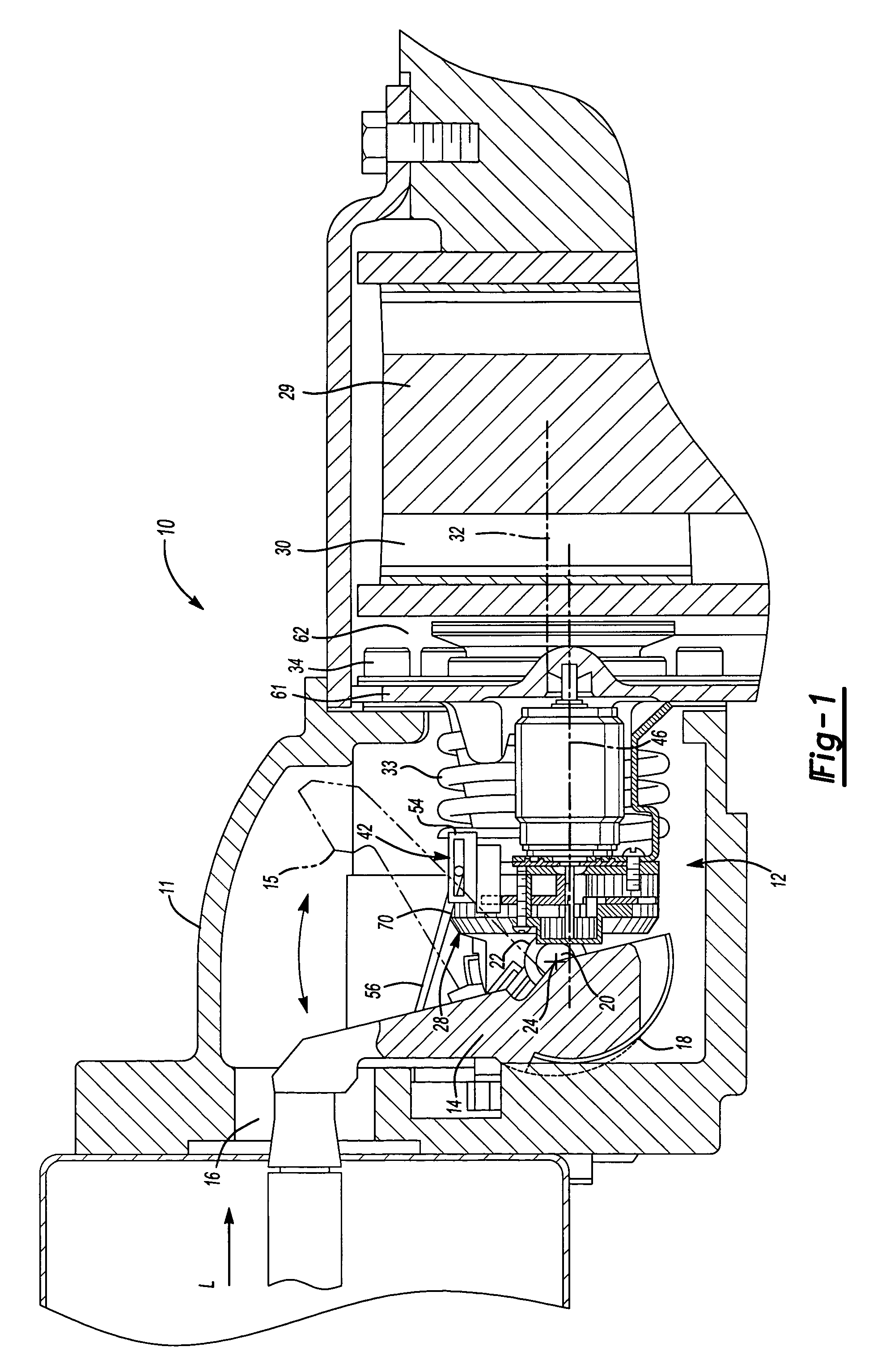
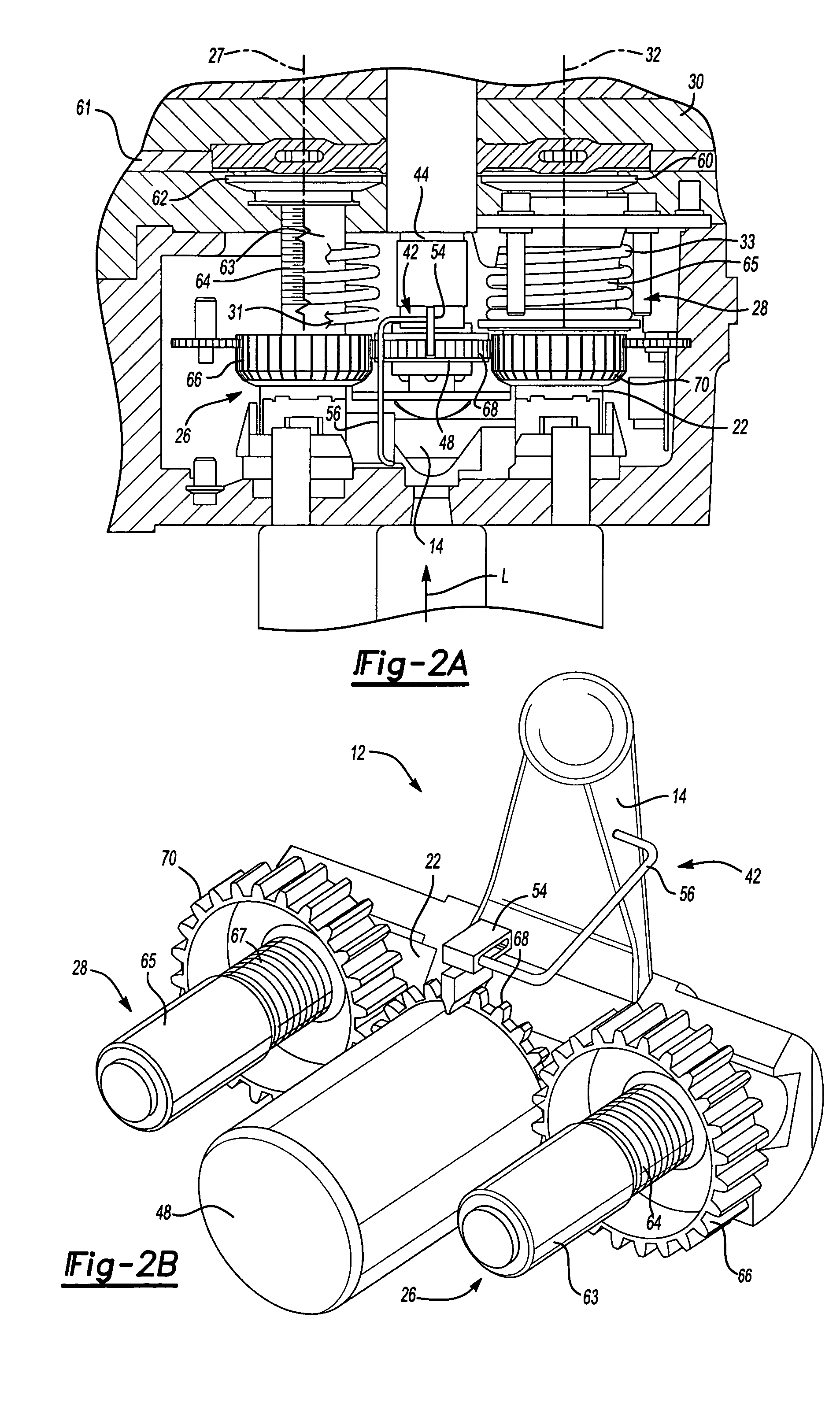
[0036]FIG. 1 illustrates a disc brake assembly 10 that utilizes a slack adjustment system 12 of the present invention. The disc brake assembly 10 has a frame 11, which encloses the internal components and bears the loads generated by them. As a driver operates a brake (not shown) an input load (illustrated by arrow L) is transferred to a lever 14, through an opening 16 in the frame 11. The lever 14 is rotatably supported by the frame 11 through a bearing 18. Applying the input load L rotates the lever 14 about a lever axis 20. That is, the lever 14 rotates clockwise about the lever axis 20, as illustrated in FIG. 1.

[0037]A cylindrical roller 22 is recessed within the base of the lever 14. The roller 22 is eccentrically centered relative the center of rotation of the lever 14. That is, the roller 22 rotates about a roller axis 24 that is offset from the lever axis 20. When the input load L causes the lever 14 to rotate about the lever axis 20 the roller 22 rotates about the roller ax...


PUM


Abstract

A slack adjustment system for a disk brake includes a biasing member to adjust slack in a brake system. The biasing member operates independently of pressure applied to a brake actuator. A locking member prevents adjustment when adjustment is not necessary. Release of the locking member allows the biasing member to adjust a resting position of brake pads independent of driver applied brake pressure.

Description

BACKGROUND OF THE INVENTION[0001]This application is a continuation in part of U.S. application Ser. No. 10 / 355,511, filed on Jan. 31, 2003 now U.S. Pat. No. 6,955,246.[0002]The present invention relates to an adjuster mechanism for a brake.[0003]As brake pads or a brake disc wear a gap between the brake pads and brake disc increases. Due to the increase in the gap between the brake pads and the brake disc a brake actuator must travel farther to engage the brake. In other words, there is more slack when the brake is applied, which causes the brakes to become less effective. In order to compensate for slack, a slack adjustment mechanism moves the brake pads closer to the brake disc prior to brake engagement. This adjustment assures a consistent amount of actuator travel in spite of brake pad wear.[0004]Conventional brake adjuster mechanisms use relatively complex mechanical assemblies to perform this function. Force from the brake actuator is commonly utilized to drive the adjuster m...

Claims


Application Information

Patent Timeline
Patent Type & Authority Patents(United States)
IPC IPC(8): F16D55/02F16D65/14F16D65/56
CPCF16D65/568F16D2121/14F16D2125/70F16D2125/32F16D2125/64F16D2125/28
Inventor NORMAN, MARK ANTHONYTAYLOR, MARTIN
Owner ARVINMERITOR TECH
Why Eureka
Try Eureka