Brush seal

a brush seal and brush technology, applied in the field of brush seals, can solve the problems of high cost, time-consuming heat treatment process, high cost, etc., and achieve the effect of reducing cost and less raw materials

Active Publication Date: 2011-04-26
RTX CORP
View PDF28 Cites 15 Cited by
  • Summary
  • Abstract
  • Description
  • Claims
  • Application Information

AI Technical Summary

Benefits of technology

[0008]It is a further object of the present invention to produce a brush seal at a reduced cost.
[0009]It is a further object of the present invention to produce a brush seal that uses less raw material.
[0010]It is a further object of the present invention to provide a brush seal that may not require heat treatment.
[0011]It is a further object of the present invention to provide a brush seal with an extended life.

Problems solved by technology

The heat treatment process is time consuming and can be expensive.
This means a mechanic must replace the entire brush seal during maintenance.
The bristle packs of the brush seal are expensive.
The main factor influencing cost is the amount of raw material used.

Method used


Image

  • Brush seal
  • Brush seal
  • Brush seal

Examples


Embodiment Construction

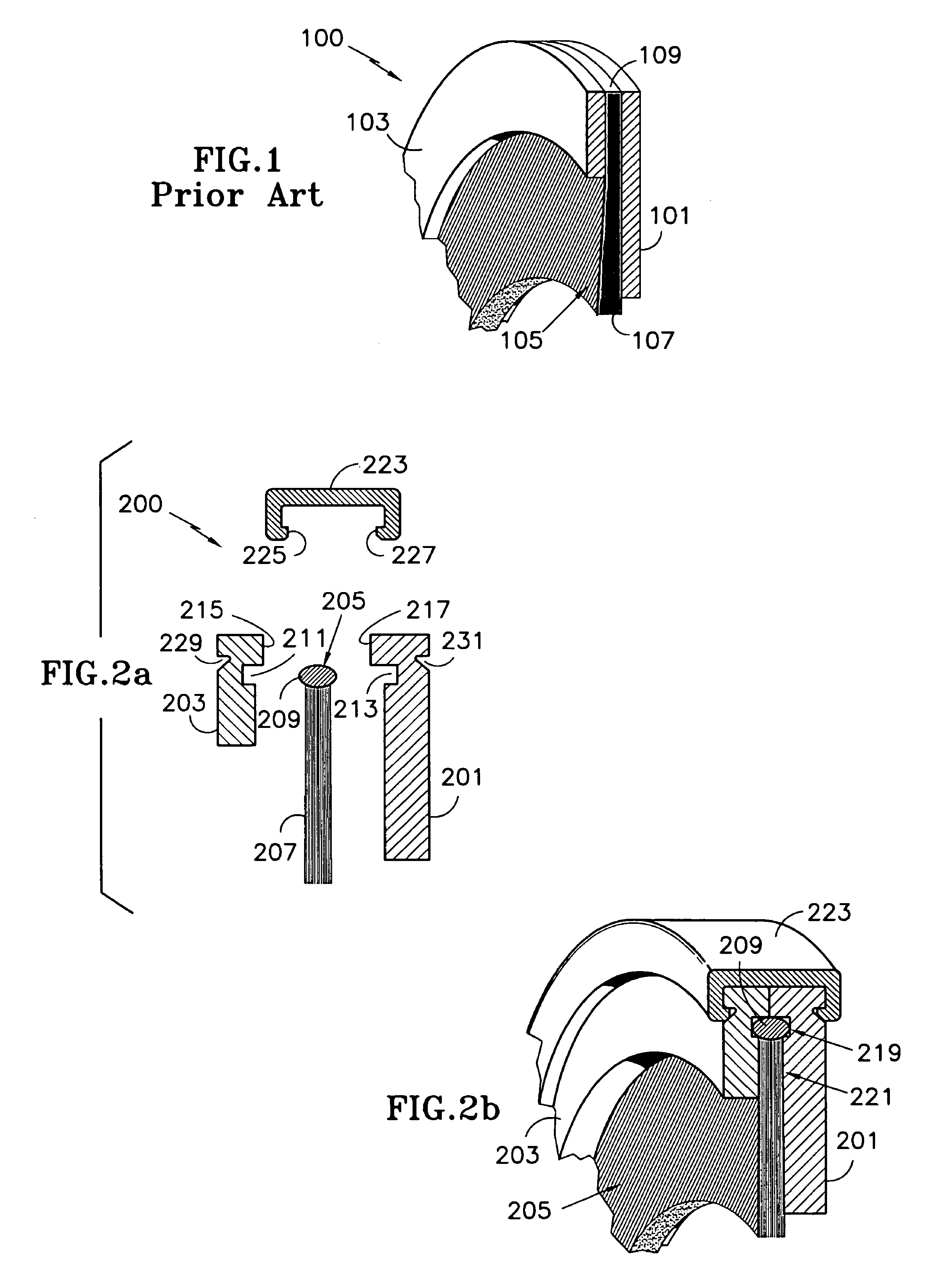
[0026]FIG. 1 displays a conventional annular brush seal 100. Although shown as a single stage, the brush seal 100 could have multiple stages. The brush seal 100 includes several sub-assemblies, namely a back plate 101 , side plate 103 and a bristle pack 105. The metal plates 101, 103 flank the bristle pack 105.

[0027]The bristle pack 105 comprises a plurality of densely arranged wire bristles. Each of the bristles has a first end 107 and an opposed second end 109. While extending at an angle to a radial line, the first ends 107 of the bristles reside at the inner diameter of the brush seal 100. The second ends 109 of the bristles reside at the outer diameter of the brush seal 100.

[0028]The plates 101,103 and the bristle pack 105 are welded together to form the brush seal 100. Specifically, the outer diameter of the plates 101, 103 and the bristle pack 105 are welded together to sandwich the bristles between the plates 101, 103.

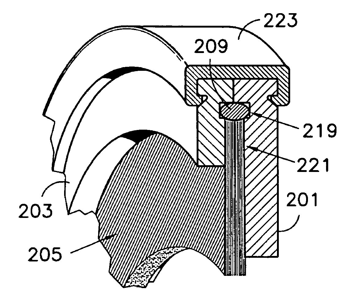
[0029]FIGS. 2a and 2b display one alternative embodiment ...


PUM


Abstract

A brush seal, comprising: a bristle arrangement with a plurality of bristles; and a joint securing the bristles together; plates flanking the bristle arrangement; and a feature on the plates to receive the joint. A brush seal, comprising: a plurality of bristles, each having a first end and an opposed second end; and plates receiving the bristles therebetween, each having a first end and a second end. The first ends of the bristles extend past the first end of the plates and the second ends of the bristles reside between the first and second ends of the plates. A method of repairing a brush seal, comprising the steps of: providing a brush seal having a bristle arrangement secured between plates; removing the bristle arrangement from the plates; providing a replacement bristle arrangement; and placing said replacement bristle arrangement between the plates.

Description

CROSS REFERENCE TO RELATED APPLICATIONS[0001]This application is related to pending United States patent application Ser. No. 10 / 074,191 filed on Feb. 12, 2002, herein incorporated by reference.BACKGROUND OF INVENTION[0002]This invention relates to brush seals. Specifically, this invention relates to the various components that form the brush seal.[0003]Brush seals are commonly used on gas turbine engines. The brush seals typically prevent secondary flow in the engine from escaping through a gap between a stationary part (e.g. a diffuser case) and a rotating part (e.g. a turbine shaft). Brush seals can have other uses, such as sealing a gap between stationary parts of the engine.[0004]A brush seal typically includes packs of wire bristles sandwiched between plates. The bristle packs and plates are typically welded together to form the brush seal. The brush seal must undergo heat treatment after the welding step to relieve any residual stresses. Heat treatment typically involves secu...

Claims


Application Information

Patent Timeline
Patent Type & Authority Patents(United States)
IPC IPC(8): F16J15/447F16J15/32
CPCF16J15/3288
Inventor SZYMBOR, JOHN A.ADDIS, MARK E.
Owner RTX CORP
Why Eureka
Try Eureka