
Automatic gearbox

a gearbox and automatic technology, applied in the direction of gearing details, mechanical equipment, gearing, etc., can solve the problem that the supply of pressure medium can be concretely implemented, and achieve the effect of preventing pressure medium loss and reducing assembly effort compared to individual variants

Active Publication Date: 2011-04-26
ZF FRIEDRICHSHAFEN AG
View PDF16 Cites 10 Cited by
  • Summary
  • Abstract
  • Description
  • Claims
  • Application Information

AI Technical Summary

Benefits of technology

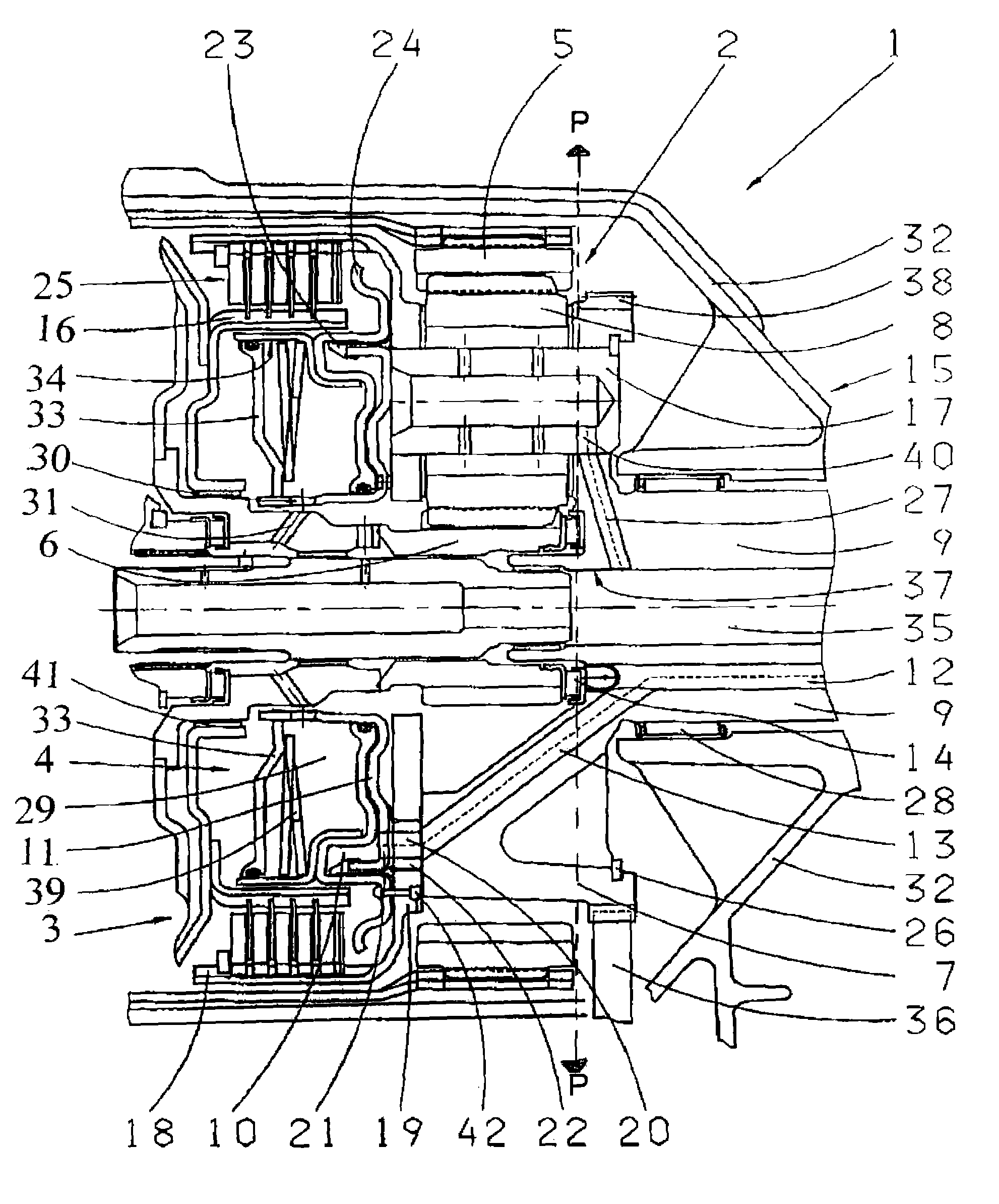
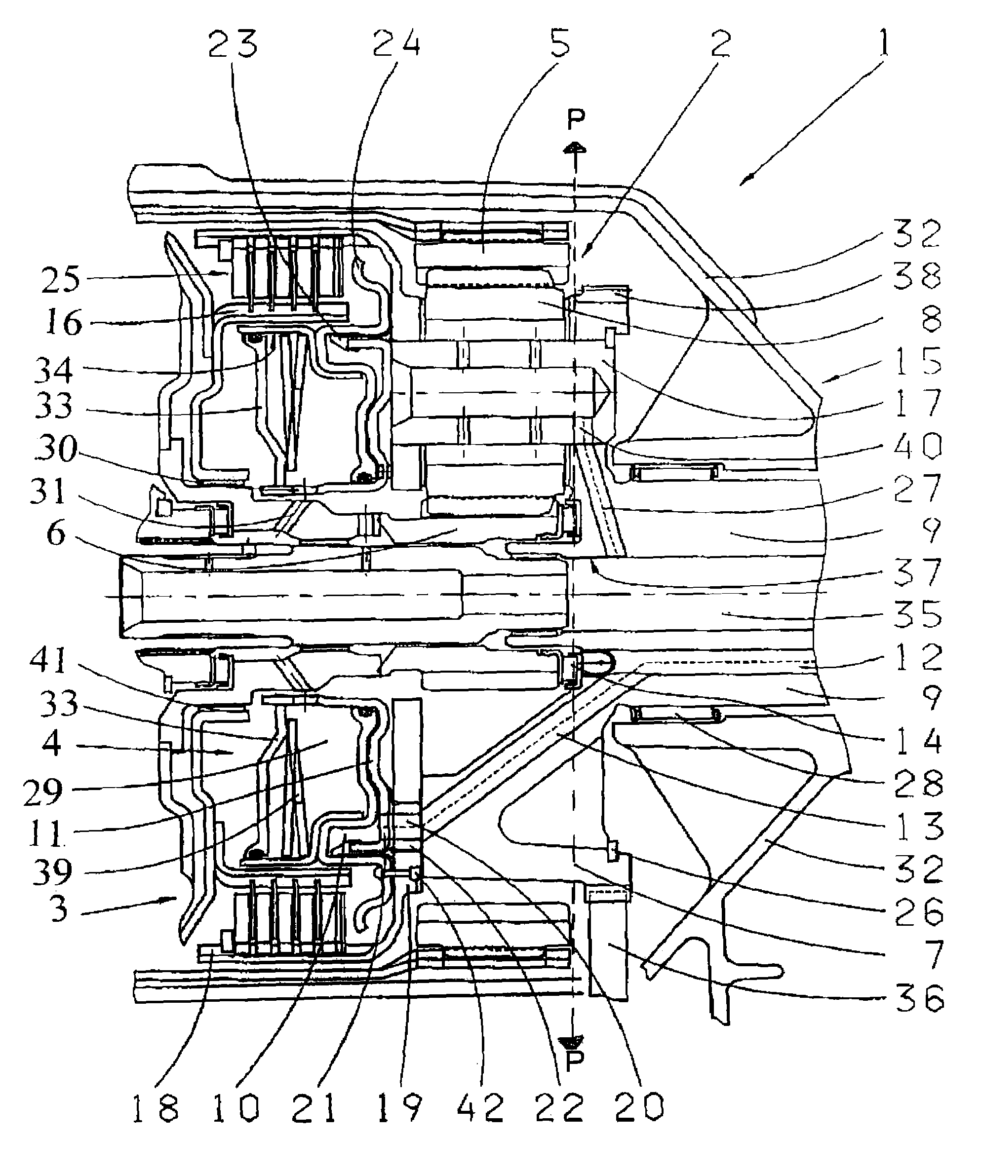
[0011]Furthermore, it is provided that an external disk support of the gear shifting element is connected in a rotationally fixed manner to the planet carrier at an axial distance to the planet gears. With this design, free rotation of the planet gears is secured and torque transmission between the external disk support and planet carrier is possible.
[0014]In order to prevent pressure medium loss along this pressure medium supply path, a further characteristic of the present invention provides that a sealing element is inserted into the bore of the guide disk, the element preventing pressure medium and / or oil from leaking out from between the cylinder and guide disk surfaces lying on top of one another as well as from the guide disk and planet carrier.
[0015]This sealing element is preferably vulcanized onto the cylinder of the piston-cylinder arrangement so that, when manufacturing a transmission of this type, the assembly effort compared to an individual variant is advantageously reduced.
[0019]According to a further embodiment of the present invention, it is provided that bores leading to the planet pins are available in the transmission shaft and / or planet carrier, the bores being likewise directed obliquely via the axial bearing associated with the transmission shaft. With this design, the lubrication of the planet gears is ensured, whereby on the one hand, comparatively short radial oblique bores in the transmission shaft are possible, and on the other hand, an adequately long axial distance to the force introduction surface of the axial bearing at the front side of the transmission output shaft is maintained. Alternatively, the planet gears can be supplied with oil via a gap between the cylinder of the piston-cylinder arrangement and the guide disk, whereby the radial area outside the planet pin must be tight and / or substantially tight.

Problems solved by technology

If, for technical reasons, in a transmission of this type the planetary stage is disposed in the transmission housing such that the pressure medium cannot be supplied to the pressure chamber of the piston-cylinder arrangement from the side of the piston-cylinder arrangement facing away from the planetary gearset, the problem arises as to how this supply of pressure medium can concretely be implemented.

Method used


Image

  • Automatic gearbox
  • Automatic gearbox

Examples


Embodiment Construction

[0024]In this FIGURE, a schematic partial cross-section of the output side of an automatic transmission 1 of the generic kind, wherein in the area of an end 15 on the output side of a transmission housing 32 a planetary stage 2, as well as axially further from this end 15, a gear shifting element 3 configured as a transmission coupling are provided.

[0025]The planetary stage 2 comprises a ring gear 5, a sun gear 6, a planet carrier 7 and planetary gears 8, which are illustrated on the upper half of the drawing.

[0026]These planetary gears 8 mesh with the ring gear 5 and the sun gear 6, while the planet carrier 7 is connected in a rotationally fixed manner to a transmission shaft 9. The sun gear 6 is configured as a sun shaft in the illustrated example and connected to further transmission parts, which are not shown in detail in the FIGURE. The planet gears 8 are each fixed firmly on the planet carrier 7 by way of planet pins 17 and mounted rotatably thereon. A radial locking ring 26, ...


PUM


Abstract

The present invention relates to an automatic transmission (1) comprising at least one planetary stage (2) and at least one gear shifting element (3), wherein this gear shifting element (3) is disposed axially directly adjacent to the planetary stage (2), wherein a piston-cylinder arrangement (4) is provided for actuating the gear shifting element (3), wherein the planetary stage (2) comprises an internal gear (5), a sun gear (6) and a planet carrier (7), on which planet gears (8) are rotatably mounted, wherein the planet carrier (7) is connected non-rotatably to a transmission shaft (9), and wherein the pressure medium can be fed to the pressure chamber (10) of the cylinder (11) of the piston-cylinder arrangement (4) through a bore (12, 13) in the transmission shaft (9) and in the planet carrier (7).

Description

[0001]This application is a national stage completion of PCT / EP2006 / 006191 filed Jun. 27, 2006, which claims priority from German Application Serial No. 10 2005 031 066.4 filed Jul. 4, 2005.FIELD OF THE INVENTION[0002]The invention relates to an automatic transmission comprising at least one planetary stage and at least one gear shifting element, wherein this gear shifting element is disposed axially directly adjacent the planetary stage, and a piston-cylinder arrangement for actuating the gear shifting element is available.BACKGROUND OF THE INVENTION[0003]If, for technical reasons, in a transmission of this type the planetary stage is disposed in the transmission housing such that the pressure medium cannot be supplied to the pressure chamber of the piston-cylinder arrangement from the side of the piston-cylinder arrangement facing away from the planetary gearset, the problem arises as to how this supply of pressure medium can concretely be implemented.SUMMARY OF THE INVENTION[0004...

Claims


Application Information

Patent Timeline
Patent Type & Authority Patents(United States)
IPC IPC(8): F16H31/00F16H57/04
CPCF16H57/0482F16H63/3026F16H57/082F16H3/54F16H2061/0046
Inventor DIOSI, GABORHAUPT, JOSEFZIEMER, PETERBREHMER, MARTIN
Owner ZF FRIEDRICHSHAFEN AG
Learn More