Ultrasonic wound debrider probe and method of use

a technology of ultrasound and wound debrider, which is applied in the field of ultrasonic surgical instruments, can solve the problems of reducing the operating time of the procedure, and achieve the effects of improving the liquid flow, reducing the bulk temperature rise of the tissue, and increasing the effectiveness of the prob

Active Publication Date: 2011-04-26
MISONIX INC
View PDF35 Cites 184 Cited by
  • Summary
  • Abstract
  • Description
  • Claims
  • Application Information

AI Technical Summary

Benefits of technology

[0008]Another relatively specific object of the present invention is to provide an improved ultrasonic surgical instrument with a form that enhances surgical efficiency and reduces the time required to complete at least some kinds of debridement procedures.
[0043]A surgical method in accordance with another feature of the present invention utilizes a probe vibratable at at least one ultrasonic frequency, where the probe has a distal end face oriented at least partially transversely to a longitudinal axis of the shaft, a lateral surface extending substantially perpendicularly to the end face and substantially parallel to the longitudinal axis, and at least one outwardly or radially extending projection extending out from the lateral surface. The method comprises bringing the lateral surface together with the projection into contact with organic tissues of a patient and, during the contacting of the tissues with the lateral surface and the projection, energizing the probe to vibrate the lateral surface and the projection at the ultrasonic frequency.

Problems solved by technology

Such energy directors, when contacting skin or tissue, will increase volume of tissue treated per unit time and thereby reduce the operating time of the procedure.

Method used


Image

  • Ultrasonic wound debrider probe and method of use
  • Ultrasonic wound debrider probe and method of use
  • Ultrasonic wound debrider probe and method of use

Examples


Embodiment Construction

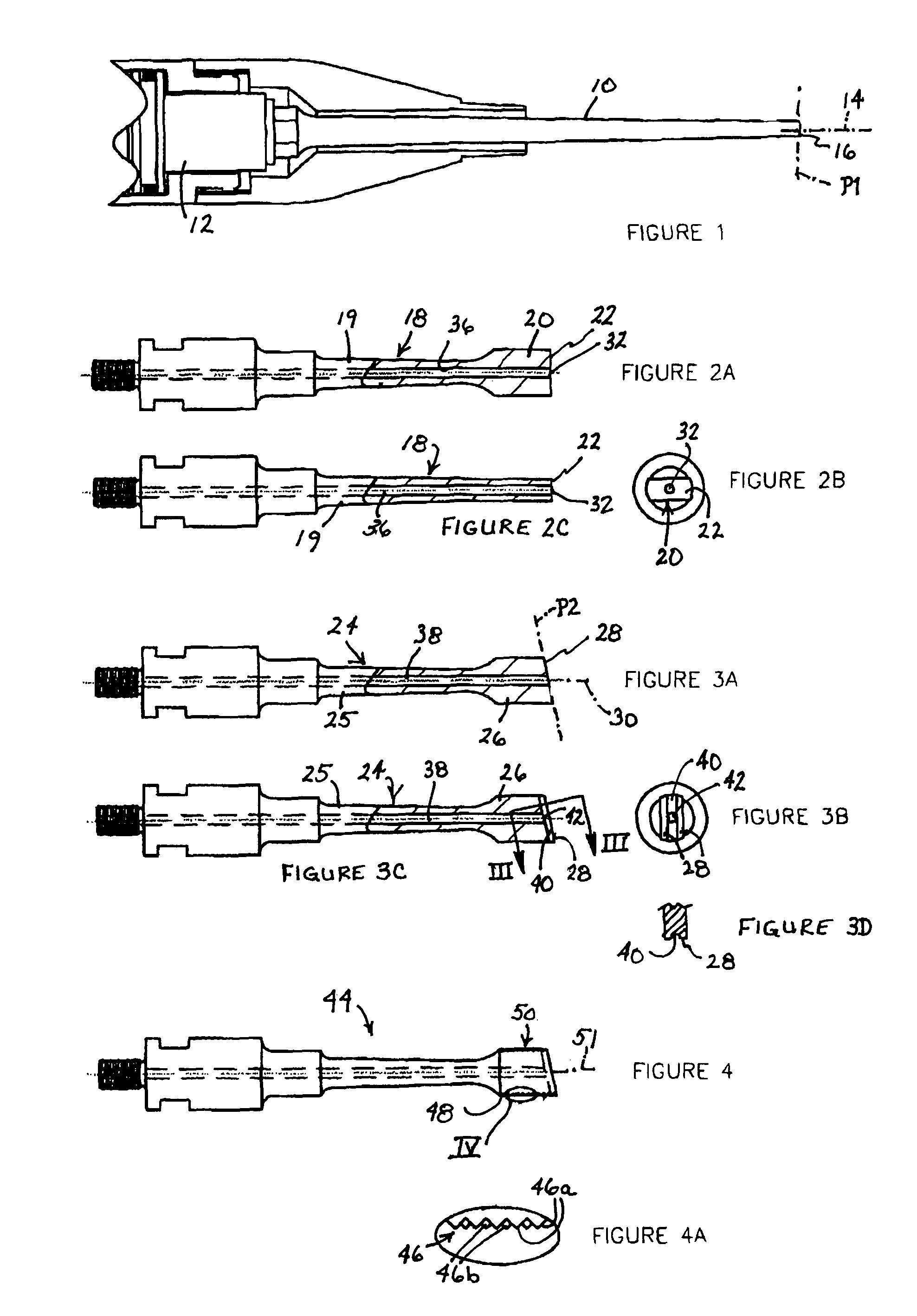
[0058]Several probes are disclosed which embody the improvements described herein. FIG. 1 shows a probe 10 which is known to the art and is currently manufactured for use with an ultrasonic aspirator. This probe 10 is basically shaped with an exponential or Gaussian taper. Probe 10 is cannulated and has an integral male thread (not shown) at the proximal end (proximate the operator). This thread communicates with a female threaded bore (not illustrated) in the transducer 12. By tightening the probe 10 onto the transducer 12 and using standard wrenches for final torquing, the transducer and probe essentially become one resonant body. Bores of the probe 10 and transducer 12 communicate with one another. The probe 10 is generally constructed of an acoustically efficient metal or ceramic. Titanium is the most commonly used material, but other material has been employed with success. Material choice does not have a significant impact upon the embodiments of this disclosure.

[0059]The dist...


PUM


Abstract

An ultrasonic medical probe comprises an elongate shaft formed integrally with a head portion having a distal end face oriented at least partially transversely to a longitudinal axis of the shaft. The shaft is provided with an internal longitudinal channel or bore extending to the end face. The end face is formed with an indentation communicating with the channel or bore at a distal end thereof, whereby liquid is guided over an extended surface of the end face relative to the channel or bore. The head portion also has a lateral surface extending substantially parallel to the longitudinal axis of the probe. The lateral surface is provided with at least one outwardly or radially extending projection. The projection enables the application of ultrasonic cavitation energy to a tissue surface that is in contact with the lateral or side surface of the probe head.

Description

BACKGROUND OF THE INVENTION[0001]This invention relates to ultrasonic surgical instruments and associated methods of use. More particularly, this invention relates to high-efficiency medical treatment probes for ultrasonic surgical aspirators. These probes increase the ability to fragment and emulsify hard and soft tissue in a clinical environment while reducing unwanted heat and collateral tissue damage.[0002]Over the past 30 years, several ultrasonic tools have been invented which can be used to ablate or cut tissue in surgery. Such devices are disclosed by Wuchinich et al. in U.S. Pat. No. 4,223,676 and Idemoto et al in U.S. Pat. No. 5,188,102.[0003]In practice, these surgical devices include a blunt tip hollow probe that vibrates at frequencies between 20 kc and 100 kc, with amplitudes up to 300 microns or more. Such devices ablate tissue by either producing cavitation bubbles which implode and disrupt cells, tissue compression and relaxation stresses (sometimes called the jackh...

Claims


Application Information

Patent Timeline
Patent Type & Authority Patents(United States)
IPC IPC(8): A61B17/20
CPCA61B17/320068A61B17/54A61B2017/320076A61B2017/22008A61B2017/00761A61B2017/320078A61B2017/32007A61B2017/320069
Inventor NOVAK, THEODORE A. D.MANNA, RONALD R.VOIC, DANISOLA, SCOTT
Owner MISONIX INC
Why Eureka
Try Eureka