Pyrolizing flexible ablator material

Inactive Publication Date: 2011-04-26
LOCKHEED MARTIN CORP
View PDF14 Cites 19 Cited by
  • Summary
  • Abstract
  • Description
  • Claims
  • Application Information

AI Technical Summary

Benefits of technology

[0012]The flexibility of this material allows it to be used to construct deployable thermal protection systems that can handle heat flux rates higher than previous deployable heat shields. In this application, a deployable system can either be an inflatable system or a mechanically unfolding one. A deployable heat shield occupies a small volume during launch, when space within the launch vehicle fairing is at a premium, and then can be expanded to a large volume after reachin

Problems solved by technology

Gas produced by pyrolysis of the heat shield material carries heat away from the spacec

Method used


Image

  • Pyrolizing flexible ablator material
  • Pyrolizing flexible ablator material
  • Pyrolizing flexible ablator material

Examples


Embodiment Construction

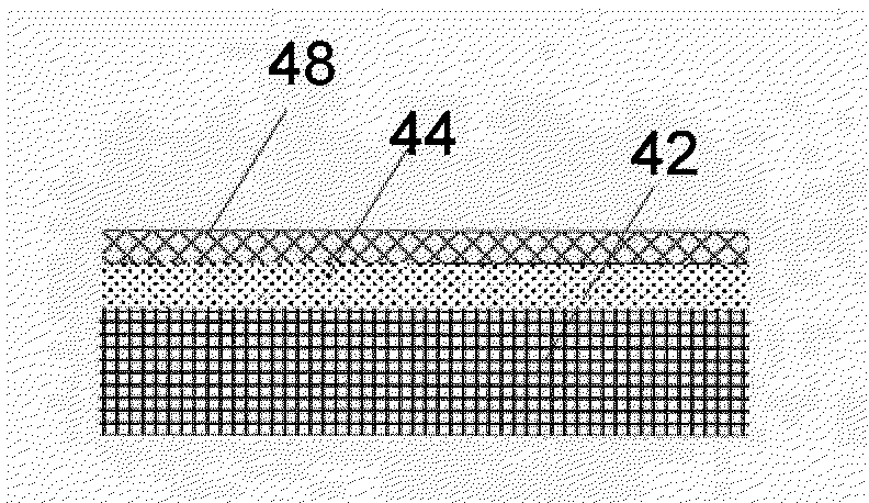
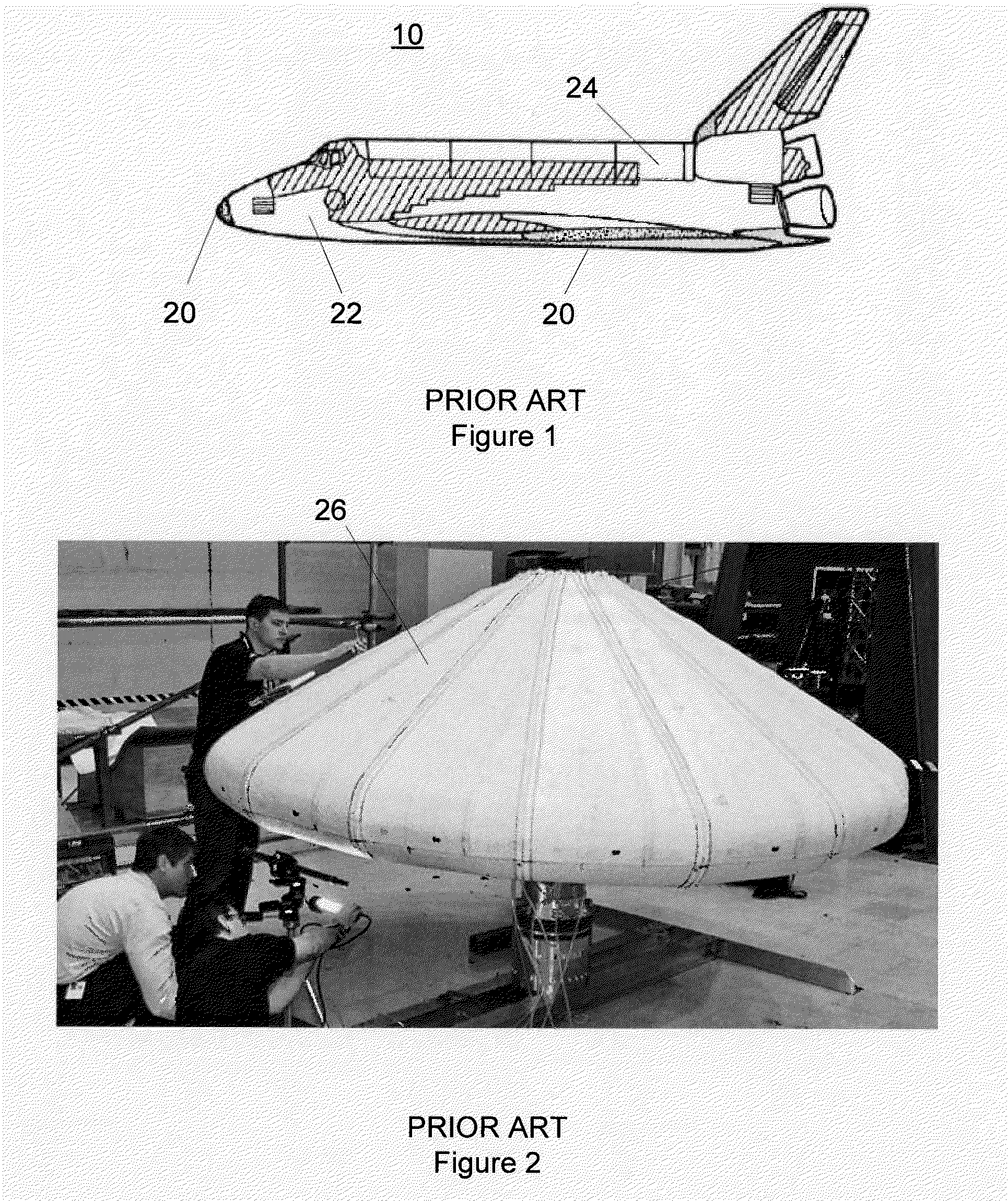
[0027]To overcome at least some of the disadvantages of the existing flexible thermal protection materials listed above, there is a need for a flexible heat shield material that can handle heat flux in excess of 5 W / cm2. In addition, it is desirable that the heat shield material have sufficient strength to enable the use of a framework support structure instead of a continuous supporting structure.

[0028]A lightweight flexible thermal protection system (TPS) is disclosed that incorporates a pyrolyzing flexible ablator and is suitable for, among other applications, reentry protection of spacecraft. Advanced reentry technology relies on lightweight TPSs to protect the vehicle from heating in the atmospheric flight. Such reentry technology can be applied to a range of missions including direct entry from deep space, reentry from low planetary orbit, and aerocapture into orbit. In addition, lightweight TPSs can make existing backshells lighter and create new opportunities for extended fo...


PUM


Abstract

A pyrolyzing flexible ablator comprising a flexible substrate and a pyrolyzing material that will pyrolize upon exposure to a heat flux greater than 5 W/cm2, the pyrolyzing material being bonded to the flexible substrate.

Description

[0001]This application claims the benefit of priority under 35 U.S.C. §119 from U.S. Provisional Patent Application Ser. No. 61 / 178,471 entitled “PYROLIZING FLEXIBLE ABLATOR MATERIAL,” filed May 14, 2009, which is incorporated by reference in its entirety for all purposes.STATEMENT REGARDING FEDERALLY SPONSORED RESEARCH OR DEVELOPMENT[0002]Not applicable.BACKGROUND[0003]1. Field[0004]The present disclosure generally relates to thermal protection materials and, in particular, to thermal protection systems using a pyrolizing ablative material.[0005]2. Description of the Related Art[0006]Every reentry spacecraft, such as an unmanned capsule or the Space Shuttle, requires some form of thermal protection if it is to survive the intense heat generated during atmospheric entry. Orbital or interplanetary spacecraft typically enter the atmosphere at hypersonic speed, creating a high-pressure bow shock wave in front of the vehicle. Within this shock wave, the compressed gas can reach temperat...

Claims


Application Information

Patent Timeline
IPC IPC(8): B32B3/26
CPCB64G1/58B64G1/62Y10S428/92Y10S428/921Y10T428/24997
Inventor WILLCOCKSON, WILLIAM H.RAWAL, SURAJ P.SONGER, JARVIS T.STOLPA, SCOTT R.
Owner LOCKHEED MARTIN CORP
Why Eureka
Try Eureka