System and method for reducing phase noise

Inactive Publication Date: 2011-04-26
AVAGO TECH INT SALES PTE LTD
View PDF27 Cites 6 Cited by
  • Summary
  • Abstract
  • Description
  • Claims
  • Application Information

AI Technical Summary

Benefits of technology

[0026]FIG. 8 is a flow diagram illustrating a method that reduces si

Problems solved by technology

Because of cost issues, high performance semiconductor processes are not normally used for such transceivers.
The noise from the resistor propagates through the non-linear function of the signal source and increases the noise profile of the signal source.
The thermal noise level close to the oscillation frequency will, therefore, grow due to the

Method used


Image

  • System and method for reducing phase noise
  • System and method for reducing phase noise
  • System and method for reducing phase noise

Examples


Embodiment Construction

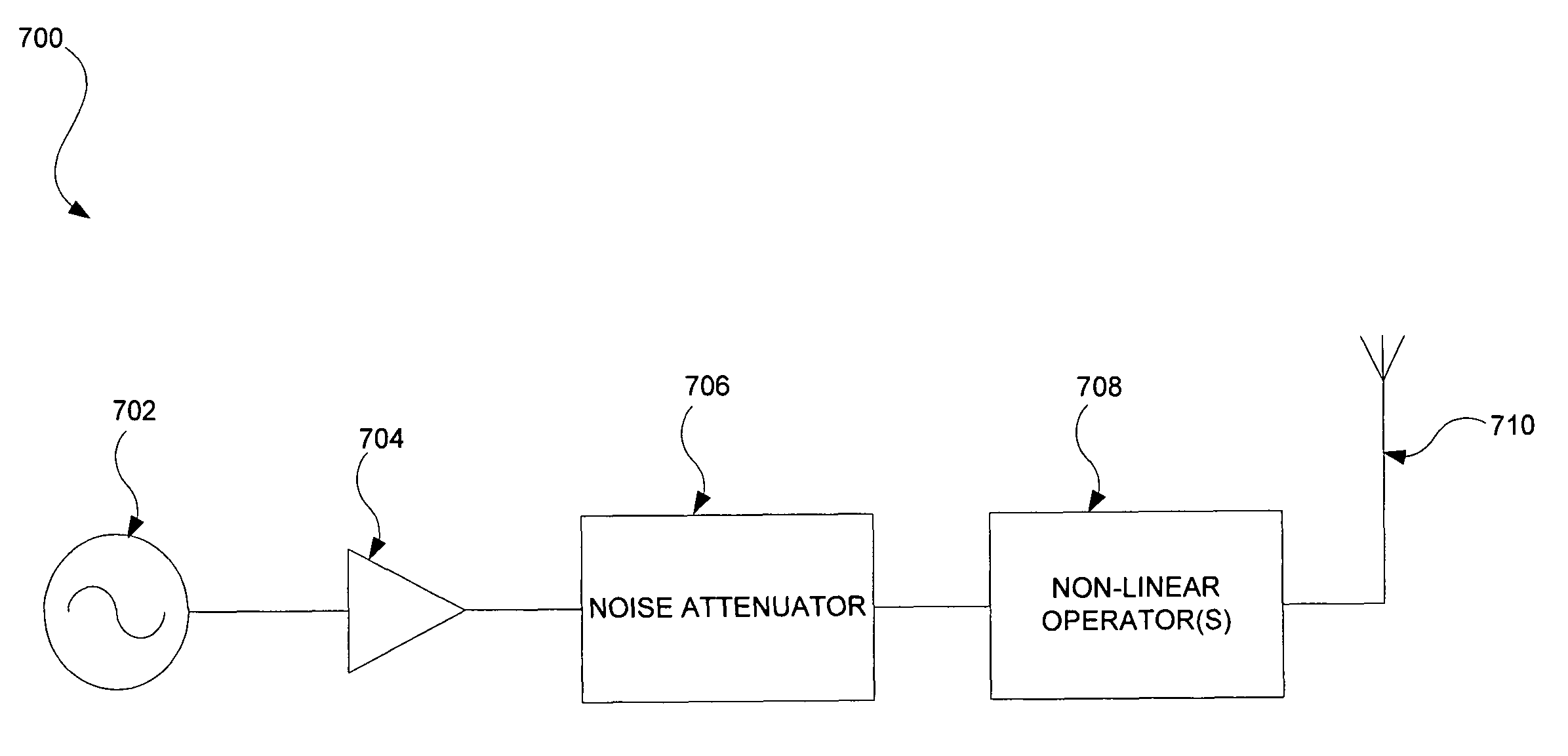
[0035]Certain aspects of the present invention may be found in, for example, systems and methods that reduce phase noise. In one embodiment according to aspects of the present invention, a method that reduces phase noise may include, for example, one or more of the following: generating a signal at a particular frequency, the signal being associated with a harmonic frequency signal disposed at a harmonic frequency; and selectively attenuating frequency content disposed in a region around the harmonic frequency. The signal may be, for example, a single-ended signal, a differential signal and / or a quadrature signal. The signal may be associated with other harmonic frequency signals disposed at respective harmonic frequencies. Frequency content disposed in a region around the respective harmonic frequencies may be selectively attenuated. One or more non-linear operations may be applied to the signal and the applied signal may be transmitted, for example, as a wireless signal (e.g., a r...


PUM


Abstract

Systems and methods that reduce phase noise are provided. In one embodiment, a method may include one or more of the following: generating a signal at a particular frequency in which the signal may be associated with a harmonic frequency signal disposed at a harmonic frequency; and selectively attenuating frequency content disposed in a region around the harmonic frequency. The signal may be associated with a second harmonic frequency signal disposed at a second harmonic frequency. Frequency content disposed in a second region around the second harmonic frequency may be selectively attenuated. One or more non-linear operations may be applied to the signal and the applied signal may be transmitted.

Description

CROSS-REFERENCE TO RELATED APPLICATIONS[0001]The present application is a continuation-in-part of application Ser. No. 09 / 634,552, filed Aug. 8, 2000 which claims benefit from and priority to Application No. 60 / 160,806, filed Oct. 21, 1999; Application No. 60 / 163,487, filed Nov. 4, 1999; Application No. 60 / 163,398, filed Nov. 4, 1999; Application No. 60 / 164,442, filed Nov. 9, 1999; Application No. 60 / 164,194, filed Nov. 9, 1999; Application No. 60 / 164,314, filed Nov. 9, 1999; Application No. 60 / 165,234, filed Nov. 11, 1999; Application No. 60 / 165,239, filed Nov. 11, 1999; Application No. 60 / 165,356; filed Nov. 12, 1999; Application No. 60 / 165,355, filed Nov. 12, 1999; Application No. 60 / 172,348, filed Dec. 16, 1999; Application No. 60 / 201,335, filed May 2, 2000; Application No. 60 / 201,157, filed May 2, 2000; Application No. 60 / 201,179, filed May 2, 2000; Application No. 60 / 202,997, filed May 10, 2000; Application No. 60 / 201,330, filed May 2, 2000. The above referenced applications a...

Claims


Application Information

Patent Timeline
IPC IPC(8): H04B1/00H03H11/12H03H21/00
CPCH03B21/01H03H11/1291H03H21/0001H03H21/0012H04B17/19H04B1/40H04B17/104H04B17/14H03J2200/10H03H2011/0494H03F3/24H04B1/0475H04B2001/0408
Inventor MOLOUDI, SHERVIN
Owner AVAGO TECH INT SALES PTE LTD
Why Eureka
Try Eureka