Prefabricated panel with protective film

a protective film and prefabricated technology, applied in the direction of container discharging methods, vessel parts, vessel construction, etc., can solve the problems of poor quality bonding, disruption of flexible sheet bonding, and a large amount of time, and achieve the effect of shortening the tim

Inactive Publication Date: 2011-05-03
GAZTRANSPORT & TECHNIGAZ SA
View PDF21 Cites 9 Cited by
  • Summary
  • Abstract
  • Description
  • Claims
  • Application Information

AI Technical Summary

Benefits of technology

[0015]As the protective portion of the film covers a region of the impervious covering that is to be bonded, this region for bonding is protected and its surface condition does not degrade or does not degrade appreciably. The quality of the bond is therefore improved. In addition, since the spew portion of the film is adjacent to the region that is to be bonded, there is no need to position adhesive tape on the panels after they have been installed. On the contrary, all that is required is for the spew portion to be removed in order to carry out the spew test. The on-site manufacturing time is thus shorter. In addition, the absence of adhesive tape makes it possible to avoid there being any non-stick product in the tank and therefore makes it possible to improve the security of the bonding.
[0019]By virtue of these features, it is possible to remove one of the four protective portions just before bonding the region that is to be bonded that it covers, without removing the other ones. Thus, the other regions for bonding remain protected as long as they are covered.
[0021]In this case, the panel can be manufactured simply by placing the single precut sheet in such a way as to produce the protective portion and the spew portion in a single step. In addition, the precut is made during the prefabrication of the panel or of the impervious covering and can therefore be positioned accurately.
[0023]By virtue of these features it is possible to choose, for the single sheet, a material that is appropriate to protecting the impervious covering, without having to give consideration to strength constraints associated with the spew test.
[0028]By virtue of these features it is possible to test the bondability of the impervious covering secured to the panel on site in a shorter space of time, and to do so for a broad region of the impervious covering. Tests known from the prior art, such as measuring the surface energy or wettability, take a great deal of time, which is incompatible with an on-site test, and only ever characterize the points measured alone.

Problems solved by technology

A damaged surface may give rise to a poor quality bond.
Before bonding the strip of flexible sheet it is necessary to place the adhesive tape on all the panels installed, and this takes a great deal of time.
In addition, the back of the adhesive tape is generally covered with a non-stick material which may migrate and greatly disrupt the bonding of the strip of flexible sheet.

Method used


Image

  • Prefabricated panel with protective film
  • Prefabricated panel with protective film

Examples


Embodiment Construction

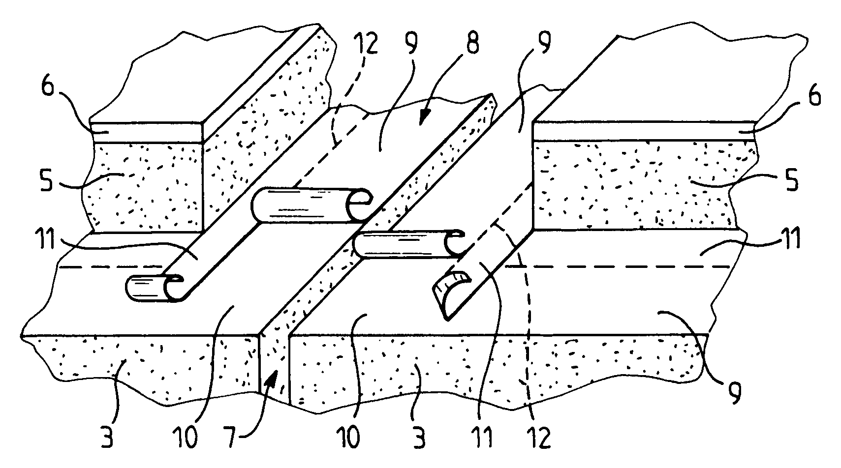
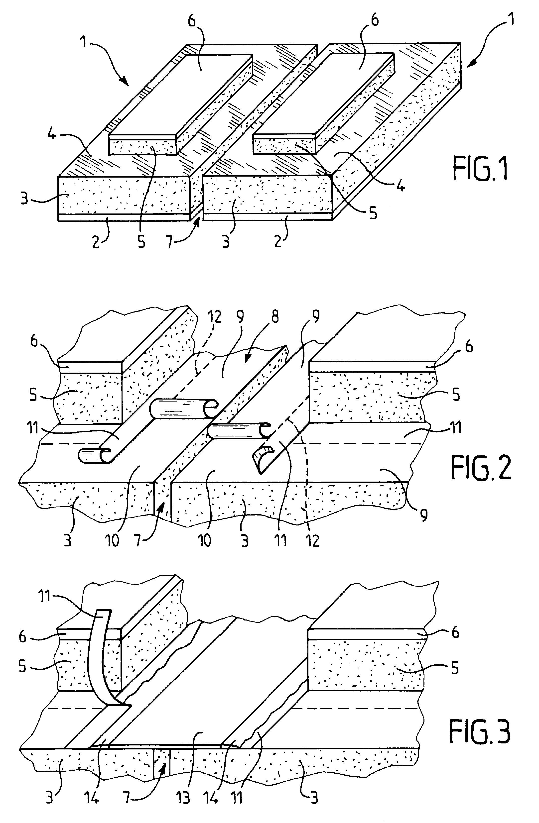
[0040]FIG. 1 depicts two prefabricated panels 1 fixed adjacent to one another on the bearing structure (not depicted) of a tank for transporting liquefied natural gas by sea.

[0041]Each panel 1 comprises a rigid backboard 2, for example made of plywood, and a first layer of thermal insulation 3, for example made of glass fibre reinforced polyurethane foam, which covers the backboard 2. The backboard 2 and the first layer of thermal insulation 3 together form a secondary thermally insulating barrier element. An impervious covering 4 is stuck to the first layer of thermal insulation 3 on the opposite side to the backboard 2. The impervious covering 4 may be rigid or flexible and comprises three layers, namely a sheet of aluminium about 0.1 mm thick, surrounded with fibreglass fabric and constitutes a secondary sealing barrier element. A second layer of thermal insulation 5, for example made of glass fibre-reinforced polyurethane foam, is bonded to the impervious covering 4, and a top b...


PUM

PropertyMeasurementUnit
thickaaaaaaaaaa
thermally insulatingaaaaaaaaaa
thicknessesaaaaaaaaaa

Abstract

Panel including, in succession, a first rigid board forming the back of the panel, a first thermally insulating layer borne by the backboard, an impervious covering covering the first thermally insulating layer, a second thermally insulating layer which partially covers the impervious covering and a second rigid board covering the second thermally insulating layer, characterized in that it includes a film which covers at least part of the impervious covering which is not covered by the second thermally insulating layer, the film including at least one protective portion and at least one spew portion adjacent to the protective portion, the protective portion and the spew portion being able to be detached from the impervious covering independently of one another.

Description

BACKGROUND OF THE INVENTION[0001]1. Field of the Invention[0002]The present invention relates to the production of sealed and thermally insulated tanks incorporated into a bearing structure, particularly the hull of a ship intended for transporting liquefied gases and, in particular, for transporting liquefied natural gases with a high methane content, by sea. More specifically, the present invention relates to a panel for manufacturing such a tank and to a method of manufacture employing this panel.[0003]2. Description of the Related Art[0004]French Patent Application No. 2 724 623 proposes a sealed and thermally insulated tank incorporated into a bearing structure, particularly of a ship. The wall of the tank exhibits, in succession from the inside of the tank towards the bearing structure, a primary sealing barrier in contact with the product contained in the tank, a primary thermally insulating barrier and a secondary sealing barrier and a secondary thermally insulating barrier....

Claims


Application Information

Patent Timeline
Patent Type & Authority Patents(United States)
IPC IPC(8): E04C2/54
CPCB32B3/06B32B5/26B32B5/32B32B15/04B32B15/14B32B15/20B32B17/02B32B17/04B32B21/08B32B21/14B32B27/04B32B27/06B32B27/12B32B27/40B63B3/68B63B25/16E04B1/80F17C13/001B32B5/18F17C2270/0107B63B9/06F17C2203/0304B63B73/46B63B73/20F17C2203/0358
Inventor DHELLEMMES, JACQUESLEFEVRE, NICOLASPREATO-PAVRET DE LA ROCHEFORDIERE, SOPHIEHUON DE KERMADEC, CHRISTOPHE
Owner GAZTRANSPORT & TECHNIGAZ SA
Why Eureka
Try Eureka