
Operator cab for heavy equipment

a technology for operators and cabs, applied in the direction of roofs, doors, wing accessories, etc., can solve the problems of reducing operation efficiency, operator cannot concentrate on work, unexpected collisions or bumpings with external obstructions such as buildings, trees,

Inactive Publication Date: 2011-05-03
VOLVO CONSTR EQUIP HLDG SWEDEN AB +1
View PDF14 Cites 13 Cited by
  • Summary
  • Abstract
  • Description
  • Claims
  • Application Information

AI Technical Summary

Benefits of technology

The solution effectively suppresses door rocking in X, Y, and Z-axis directions, enhancing operator focus and safety, reducing manufacturing costs, and improving the equipment's external appearance by minimizing stopper protrusion and allowing for adjustable stopper positioning.

Problems solved by technology

During a swinging operation of the equipment in a state that a hinge type door of the cab is kept open in a narrow or limited working environment such as a downtown area, unexpected collision or bumping with external obstructive objects such as buildings, trees, and so forth, may occur.
As a result, an operator cannot concentrate upon his work to lower the operation efficiency and to cause the occurrence of a safety accident.
This causes the number of components and their assembling time and process to be increased with the cost raised.
However, the shock or vibration generated in the upward / downward direction of the door 3 (i.e., Z-axis direction in the drawing) cannot be effectively suppressed.
Also, the shock or vibration generated in the right / left direction of the door 3 (i.e., Y-axis direction in the drawing) cannot be effectively suppressed.

Method used


Image

  • Operator cab for heavy equipment
  • Operator cab for heavy equipment
  • Operator cab for heavy equipment

Examples


Embodiment Construction

[0064]Hereinafter, a preferred embodiment of the present invention will be described with reference to the accompanying drawings. The matters defined in the description, such as the detailed construction and elements, are nothing but specific details provided to assist those of ordinary skill in the art in a comprehensive understanding of the invention, and thus the present invention is not limited thereto.

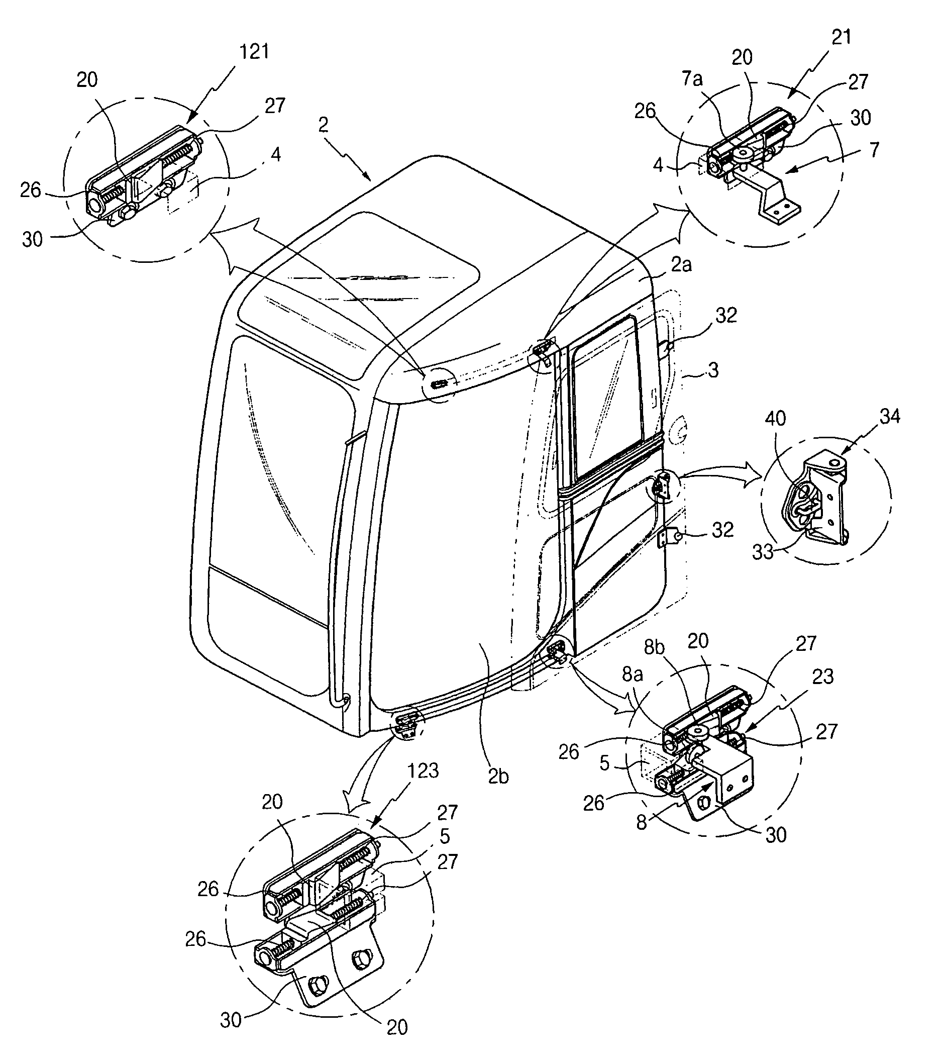
[0065]In FIGS. 4, 5, 6, 8, and 9, an operator cab for heavy equipment according to an embodiment of the present invention is illustrated. When a sliding door 3 is fully opened, it is prevented from rocking by an upper stopper 21 and a lower stopper 23.

[0066]The operator cab 2 according to an embodiment of the present invention includes an outer sidewall 2a having a doorway 2b formed thereon and an outer surface that is in an arc shape; upper and lower rails 4 and 5 provided on upper and lower portions of the outer sidewall 2a, respectively; a sliding door 3 being slid by upper and...


PUM


Abstract

An operator cab for heavy equipment is disclosed to prevent a sliding door mounted on the cab from rocking or rattling in X, Y, and Z-axis directions due to a shock or vibration applied to the cab in a state that the sliding door is fully opened or closed. The operator cab includes an outer sidewall having a doorway formed thereon; upper and lower rails provided on upper and lower portions of the outer sidewall; a sliding door being slid by upper and lower rollers engaged with the upper and lower rails; an upper stopper of an opened position, installed in the opened position of the outer sidewall, for being in contact with the upper roller when the sliding door is fully opened, to prevent the sliding door from rocking when the upper stopper becomes in contact with the upper roller; and a lower stopper of an opened position, installed in the opened position of the outer sidewall, for being in contact with the lower roller when the sliding door is fully opened, to prevent the sliding door from rocking when the lower stopper becomes in contact with the lower roller.

Description

CROSS-REFERENCE TO RELATED APPLICATION[0001]This application is based on and claims priority from Korean Patent Application No. 10-2006-109930, filed on Nov. 8, 2006 in the Korean Intellectual Property Office, the disclosure of which is incorporated herein in its entirety by reference.BACKGROUND OF THE INVENTION[0002]1. Field of the Invention[0003]The present invention relates to an operator cab for heavy equipment capable of preventing a sliding door from rocking or rattling due to vibration and so on being transferred to the cab in a state that the sliding door mounted on the cab is fully opened or closed.[0004]More particularly, the present invention relates to an operator cab for heavy equipment capable of preventing a sliding door from rocking or rattling in X, Y, and Z-axis directions due to a shock or vibration applied to the cab when the sliding door is in an open or closed state.[0005]Here, the X-axis direction as described above means a forward / backward direction of the ca...

Claims


Application Information

Patent Timeline
Patent Type & Authority Patents(United States)
IPC IPC(8): B60J5/06
CPCB60J5/062B60J5/06E05Y2800/422E05F5/003E05D15/1047E05Y2201/64E02F9/16E02F9/00
Inventor KIM, KANG TAEKOSAKA, HIDEOUCHIDA, YASUSHI
Owner VOLVO CONSTR EQUIP HLDG SWEDEN AB
Learn More