Torque control circuit for electrical motor

a torque control circuit and motor technology, applied in the direction of electric variable regulation, process and machine control, instruments, etc., can solve the problems of insufficient accuracy and timeliness in measuring the rotational speed, inability to monitor current flowing through the electrical motor as a basis for torque control, and insufficient voltage applied to the electrical motor. achieve superior and precise torque control, simplify and low-cost control circuit, and protect battery over-discharge

Inactive Publication Date: 2011-05-03
MOBILETRON ELECTRONICS
View PDF11 Cites 17 Cited by
  • Summary
  • Abstract
  • Description
  • Claims
  • Application Information

AI Technical Summary

Benefits of technology

[0009]Since the current is the candidate for control, a linear circuit would be adequate enough for this purpose. The problem of heavy noises produced by the electrical motor is therefore avoided.
[0011]The combination of the constant current circuit and the microprocessor could provide an additional benefit in battery over-discharge protection. Based on the monitored voltage, the microprocessor could determine the maximum allowable current drawn from the battery so that the battery is not overly discharged.
[0012]In summary, the present invention uses linear circuit in dynamic detection and electrical motor control, and uses a microprocessor for setting the parameters of the linear circuit. The present invention therefore could achieve superior and precise torque control with a significantly simplified and low-cost control circuit.

Problems solved by technology

This approach has a number of disadvantages such as the resolution (thereby, the accuracy) and timeliness in measuring the rotational speed are both insufficient.
However, in reality, the voltage applied to the electrical motor is not constant, especially when the electrical motor is powered by a battery.
Taking Li battery as an example, its output voltage and current has a corresponding curve and the monitored current to the electrical motor alone does not accurately reflect the power input to the electrical motor.
Due to these factors, monitoring current flowing through the electrical motor as a basis for torque control is rather inaccurate.
However, it would be too complicated to achieve this aim by only using linear circuits.
Unfortunately, a logic circuit operating around an electrical motor usually suffers heavy noises.
To avoid these noises causing misjudgments, a complex filter circuit has to be implemented, which would inevitably introduce time delay into torque control.
Together with the time required for calculation the right torque level, the timeliness of this approach is significantly compromised.

Method used


Image

  • Torque control circuit for electrical motor
  • Torque control circuit for electrical motor
  • Torque control circuit for electrical motor

Examples


first embodiment

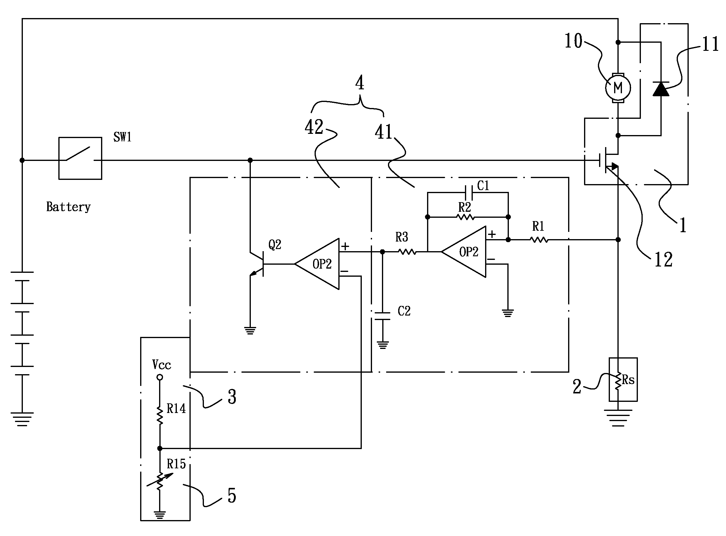
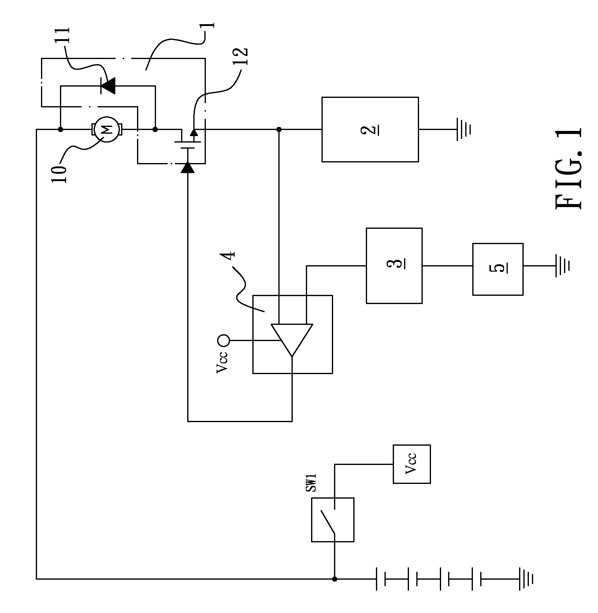
[0020]FIG. 1 is a block diagram showing a torque control circuit according to the present invention. As illustrated, the present embodiment basically contains a motor driving circuit 1, a current detection circuit 2, a reference voltage generation circuit 3, a current limiting circuit 4, and a torque configuration circuit 5. The motor driving circuit 1 drives a motor 10 and is series-connected to the current detection circuit 2 and ground in this order. The current limiting circuit 4 has two inputs, a first input terminal connected to the junction between the motor driving circuit 1 and the current detection circuit 2, and a second input terminal connected to the reference voltage generation circuit 3 and the torque configuration circuit 5 (so as to receive a reference voltage). An output terminal of the current limiting circuit 4 is connected to a control terminal of the motor driving circuit 1 (to turn on or off the motor driving circuit 1).

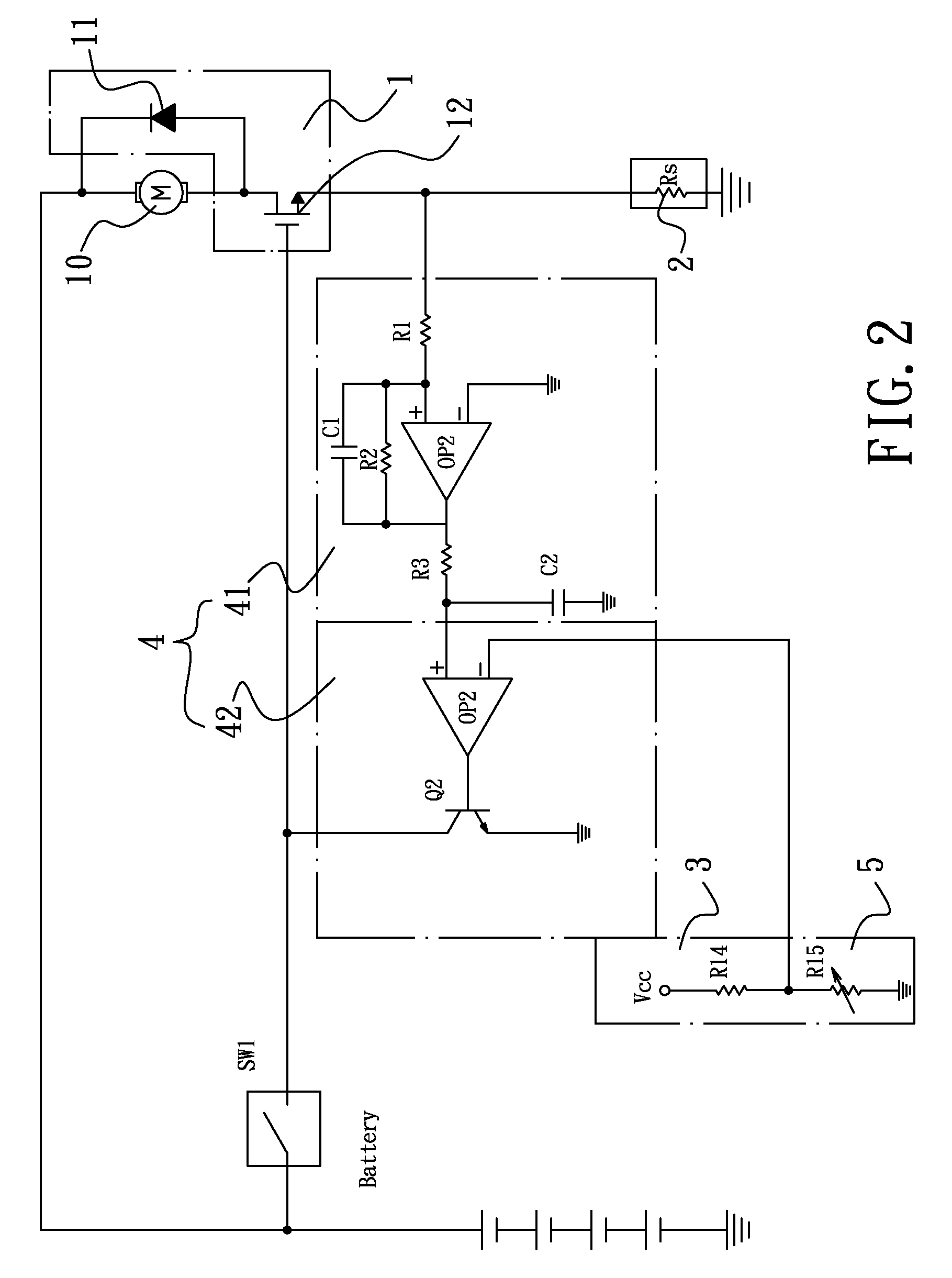
[0021]FIG. 2 is a circuit diagram showin...

second embodiment

[0026]FIG. 3 is a block diagram showing a torque control circuit according to the present invention. As illustrated, the present embodiment also contains the motor driving circuit 1, the current detection circuit 2, the reference voltage generation circuit 3, the current limiting circuit 4, and the torque configuration circuit 5, similar to the previous embodiment. Additionally, there are a display circuit 6, a voltage regulating circuit 7, a control circuit 9, and a temperature sensor circuit 8. Please note that the temperature sensor circuit 8 could be omitted in some embodiments. The control circuit 9 mainly contains a controller IC having a number of input and output terminals. The outputs of the reference voltage generation circuit 3, the current limiting circuit 4, the torque configuration circuit 5, and the temperature sensor circuit 8 are connected to appropriate input terminals of the control circuit 9, respectively. The control circuit 9 then sends control signals via appr...


PUM


Abstract

The torque control circuit of a hand tool contains a motor driving circuit, a current detection circuit, a reference voltage generation circuit, a current limiting circuit, and a torque configuration circuit. In the last stage of operation of the hand tool and when the average current has reached a predetermined level, the average current is maintained for a period of time to provide a constant average power and therefore to achieve an appropriate tightness of the bolt or nut being operated. The detection and control of current is achieved by a linear circuit which is robust to the heavy noises produced by the motor. A microprocessor is adopted to consider factors such as temperature in determining a suitable current level.

Description

TECHNICAL FIELD OF THE INVENTION[0001]The present invention generally relates to electrical motors, and more particularly to a torque control circuit for an electrical motor of a hand tool.DESCRIPTION OF THE PRIOR ART[0002]Electrical hand tools such as screw drivers and wrenches usually contains an internal direct-current (DC) electrical motor providing rotational force to a bolt or nut. In tightening the bolt or nut, usually the hand tool has to deliver a specific torque in the last stage so that the bolt or nut could be appropriately fastened, without being too loosed or too tight.[0003]When resistance is encountered during the course of the electrical motor's operation, its rotational speed would be reduced. A conventional approach is therefore to adjust the output torque of the electrical motor in accordance with the monitored rotational speed of the electrical motor. This approach has a number of disadvantages such as the resolution (thereby, the accuracy) and timeliness in mea...

Claims


Application Information

Patent Timeline
Patent Type & Authority Patents(United States)
IPC IPC(8): H02P7/00
CPCH02P7/295
Inventor WEI, CHEN-KU
Owner MOBILETRON ELECTRONICS
Why Eureka
Try Eureka