Photoelectric converter, detector and scanning equipment

A photoelectric converter and detector technology, applied in the field of nuclear medicine imaging, can solve the problems of high price of position-sensitive photomultiplier tubes, increase the cost of PET system, etc., and achieve the effects of low cost, small size, and improved flexibility

Active Publication Date: 2016-06-08
RAYCAN TECH CO LTD SU ZHOU
View PDF2 Cites 27 Cited by
  • Summary
  • Abstract
  • Description
  • Claims
  • Application Information

AI Technical Summary

Problems solved by technology

However, position-sensitive photomultiplier tubes are very expensive and will increase the cost of the PET system

Method used


Image

  • Photoelectric converter, detector and scanning equipment
  • Photoelectric converter, detector and scanning equipment
  • Photoelectric converter, detector and scanning equipment

Examples


Embodiment 1

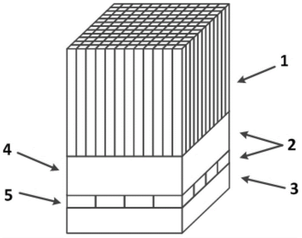
[0048] Such as figure 1 As shown: the detector includes a scintillation crystal 1 , a photoelectric converter 2 , and an electronic system 3 . The scintillation crystal 1 is formed by splicing 12×12 scintillation crystal strips of the same size on a horizontal plane. The bottom surface of the scintillation crystal 1 is directly coupled to the top surface of the light guide 4, and the silicon photomultiplier tube array 5 consists of 4×4 silicon photomultiplier tubes of the same size, wherein the light guide has only one layer, the shape is a cuboid, the material is glass, and the thickness is 13mm. In Electronics System 3, the DPC circuit is firstly used to reduce the number of channels from 16 to 4, and then the Anger-Logic algorithm is used to obtain the deposition position of the γ photon; and, the time to extract the summed signal is the deposition time of the γ photon.

Embodiment 2

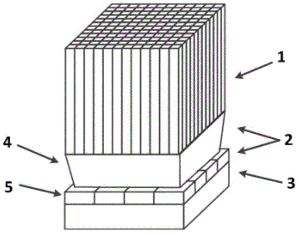
[0050] Such as figure 2 As shown: the detector includes a scintillation crystal 1 , a photoelectric converter 2 , and an electronic system 3 . The scintillation crystal 1 is formed by splicing 12×12 scintillation crystal strips of the same size on a horizontal plane. The bottom surface of the scintillation crystal 1 is directly coupled with the top surface of the light guide 4. The silicon photomultiplier tube array 5 consists of 4×4 silicon photomultiplier tubes of the same size, wherein the light guide is only one layer, and its shape is a quasi-conical hexahedron. They are all square, the four sides are trapezoidal, the square areas of the upper and lower surfaces are different, and the thickness is 13mm. In Electronics System 3, the cross-wire circuit is first used to reduce the number of channels from 16 to 8, and then the maximum likelihood estimation method is used to obtain the deposition position of the gamma photon; the method of obtaining the deposition time infor...

Embodiment 3

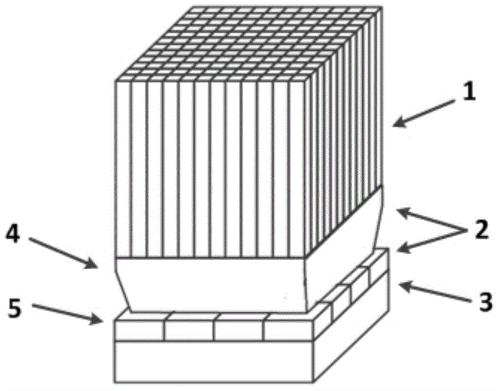
[0052] Such as image 3Shown: A position-sensitive PET detector based on a silicon photomultiplier tube includes a scintillation crystal 1 , a photoelectric converter 2 , and an electronics system 3 . The scintillation crystal 1 is formed by splicing 12×12 scintillation crystal strips of the same size on a horizontal plane. The bottom surface of the scintillation crystal 1 is directly coupled with the top surface of the light guide 4, and the silicon photomultiplier tube array 5 is composed of 4×4 silicon photomultiplier tubes of the same size, wherein the light guide is only one layer, and its shape is a quasi-conical decahedron, that is, a A cuboid plus a hexahedron (with a continuous light guide in the middle), the upper and lower surfaces of the entire decahedron are squares with different surface areas, and the sides are four rectangles plus four trapezoids, with a total thickness of 13mm. In Electronics System 3, the cross-wire circuit is first used to reduce the number...


PUM


Abstract

The invention relates to a photoelectric converter, a detector and scanning equipment. The photoelectric converter comprises a silicon photomultiplier array and a light guide coupled with the silicon photomultiplier array, wherein the silicon photomultiplier array comprises i*j silicon photomultipliers spliced on a horizontal plane, and the i and the j are both integers greater than or equal to 2. The detector comprises a scintillation crystal, an electronic system, a light guide and silicon photomultipliers. The scanning equipment comprises a detection device and a frame, wherein the detection device comprises the detector, and the detector comprises the photoelectric converter. According to the photoelectric converter, the detector and the scanning equipment, a photoelectric conversion scheme of the photoelectric silicon photomultipliers is mainly employed, the silicon photomultipliers have small volumes and are closely arranged, the silicon photomultipliers in proper dimensions and in proper quantity are matched with the light guide in proper shape, a PET detector with high spatial resolution can be established, so the spatial resolution of the whole PET system can be improved, the PET detector having DOI and TOF performances is proper to establish, application to PET/MRI can be realized, and low cost is further realized.

Description

technical field [0001] The invention relates to the technical field of nuclear medicine imaging, in particular to a photoelectric converter, a detector with the photoelectric converter and a scanning device with the detector. Background technique [0002] The Positron Emission Tomography (PET) detector is the key device in the PET imaging equipment, and its main function is to obtain the position, time and energy information of the gamma photon deposition in the PET system. The performance of the PET detector directly determines the performance of the entire PET imaging system. In order to improve the imaging performance of the system, it is hoped that the positron emission tomography imaging detector used has high spatial resolution, good time resolution, and good energy resolution. Features such as high count rate. [0003] The function of the photoelectric converter in the PET detector is to convert the scintillation photons output by the front-end scintillation crystal ...

Claims


Application Information

Patent Timeline
Patent Type & Authority Applications(China)
IPC IPC(8): H01L31/107G01T1/202
CPCH01L31/107G01T1/248G01T1/1642G01T1/2002H01L31/02327
Inventor 谢庆国朱俊牛明王璐瑶
Owner RAYCAN TECH CO LTD SU ZHOU
Why Eureka
Try Eureka