This helps you quickly interpret patents by identifying the three key elements:
Problems solved by technology
Method used
Benefits of technology
Benefits of technology
[0009] On the other hand, in the soundproofing structure described in Patent Document 2, a fan is disposed sideways and an intake opening portion is formed in an upper surface of a body cover and a duct for connection between the fan and the intake opening portion is largely bent at an angle of 90° or more within a narrow region. Consequently, not only the air flow resistance increases, but also noise is muffled in the central portion of the machine body and reflects upward, thus giving rise to the problem that a louder noise is generated upward or the muffled noise is propagated to a cabin to increase the internal noise of the cabin without reducing the cooling performance.
[0026] A sound absorbing material may be affixed to the guide means and a splitter or cell type sound deadening device may be incorporated within the duct. Moreover, an air guide plate for guiding cooling air introduced from the air-intake opening portion to the heat exchanger side may be provided within the duct and a sound absorbing material may be affixed to the air guide plate. As a result, it is possible to obtain a more outstanding engine noise reducing effect.
Problems solved by technology
In such an arrangement, however, since the radiator and the exhaust air port are shifted from each other, the radiator must be positioned higher than the usual position thereof, with an inconvenient result that an upper surface of a body cover must be set high accordingly.
Consequently, not only the air flow resistance increases, but also noise is muffled in the central portion of the machine body and reflects upward, thus giving rise to the problem that a louder noise is generated upward or the muffled noise is propagated to a cabin to increase the internal noise of the cabin without reducing the cooling performance.
Method used
Image
Click on the blue label to locate the original text in one second.
Reading with bidirectional positioning of images and text.
Examples
third embodiment
[0080]FIG. 7 illustrates a low noise structure according to the present invention.
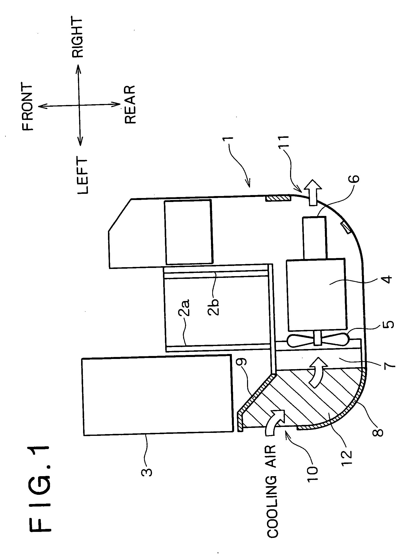
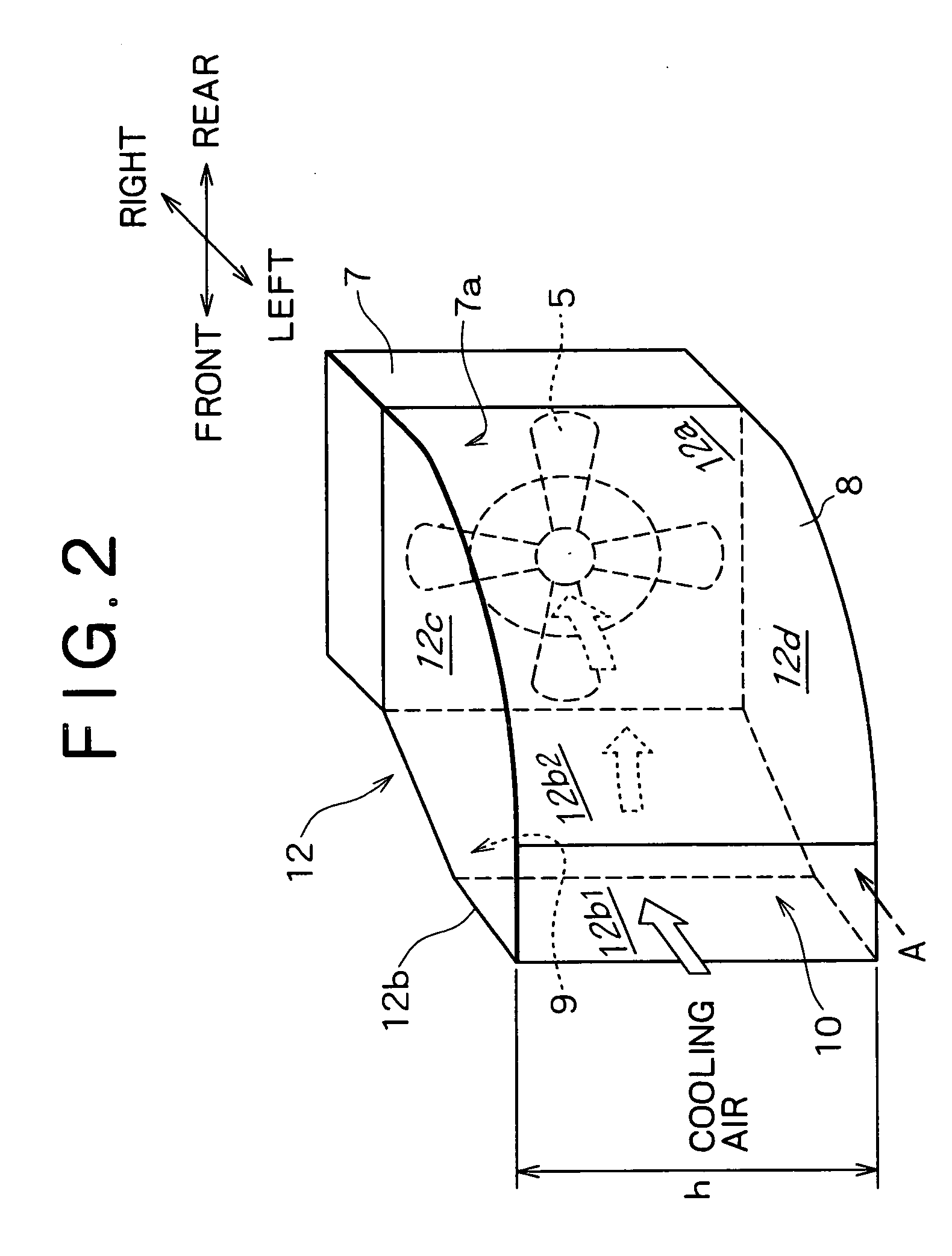
[0081] In the low noise structure shown in FIG. 7, as in the above embodiments, the air-intake opening portion 10 is formed in a side face of the machine body and at a position offset obliquely forward from the radiator 7.
[0082] The air-intake opening portion 10 and the radiator 7 are connected together by the duct 12 and a part of an engine guard 17 which constitutes a front face of the duct 12 is formed in an arcuate shape.
[0083] Plural air guide plates 18 are disposed along the arcuate shape of the engine guard 17.
[0084] With the air guide plates 18 thus disposed near the air-intake opening portion 10 in the duct 12, cooling air can be introduced extremely smoothly into the machine body and the cooling air thus introduced can be introduced into the radiator 7 while its flow is kept uniform by the air guide plates 18. Consequently, even without an intake side opening in the front face of the radia...
fourth embodiment
[0085]FIG. 8 illustrates a low noise structure according to the present invention.
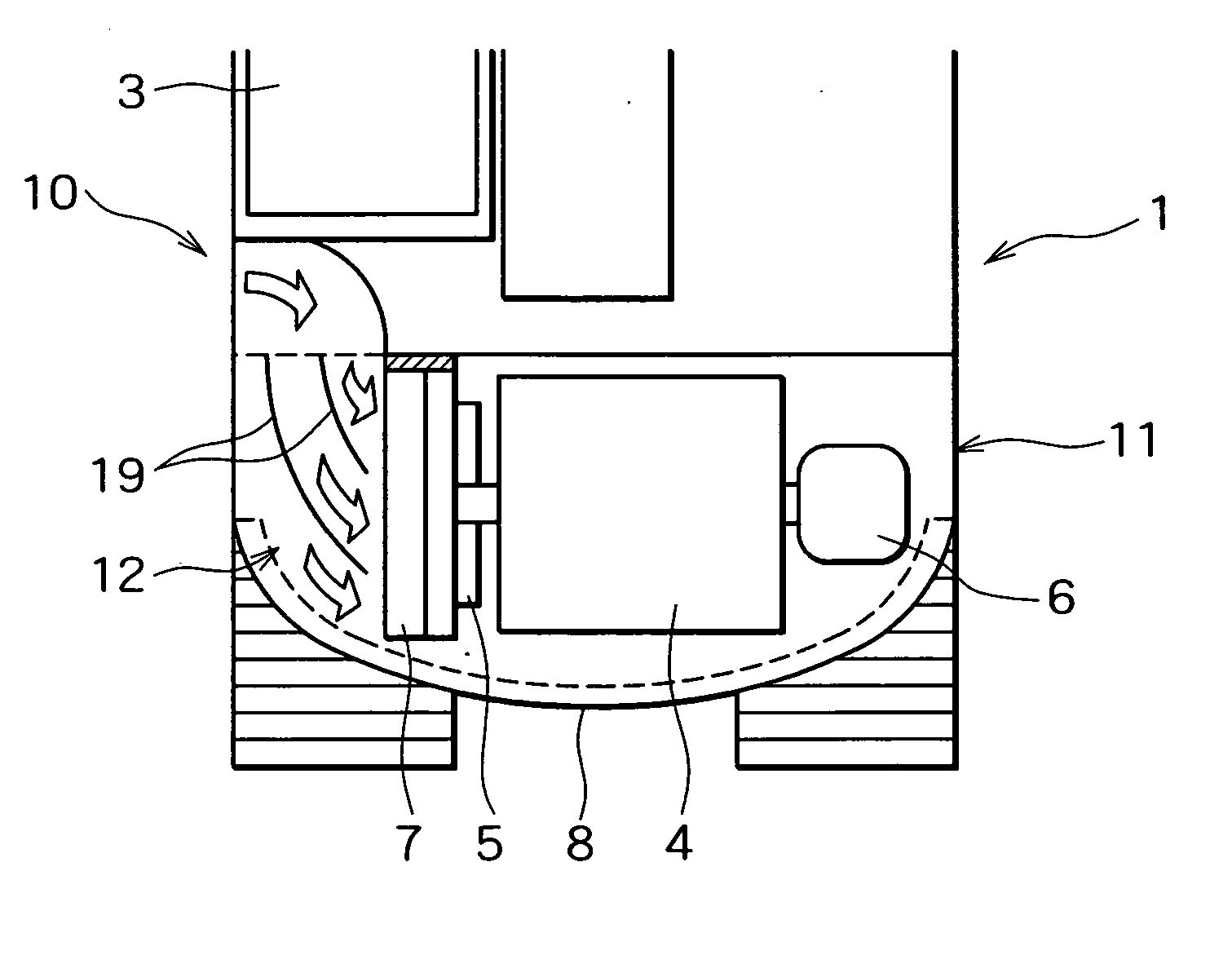
[0086] In the low noise structure shown in FIG. 8, plural air guide plates 19 are disposed within the duct 12 so as to be positioned upstream of and near the radiator 7.
[0087] The air guide plates 19 are each formed in an arcuate shape so that the cooling air taken in from the air-intake opening portion 10 is introduced smoothly into the radiator 7.
fifth embodiment
[0088]FIG. 9 illustrates a low noise structure according to the present invention.
[0089] In the low noise structure shown in FIG. 9, the air guide plates 18 shown in FIG. 7 and the air guide plates 19 shown in FIG. 8 are connected together into air guide partitioning plates 20 to guide cooling air from the intake side opening 10 of the duct to the radiator 7.
[0090] By providing the air guide plates 18 or 19 or the air guide partitioning plates 20 in the duct 12, as described above, cooling air can be introduced efficiently into the radiator 7 even if the air-intake opening portion 10 and the radiator 7 are not opposed to each other.
[0091] If a sound absorbing material is affixed to the surfaces of the air guide plates 18, 19 and the air guide partitioning plates 20 and also to the inner wall of the duct 12, it is possible to attain a further reduction of noise.
[0092] Although in the above embodiments the air-intake opening portion 10 and the radiator 7 are connected together by t...
PUM
Abstract
Engine noise of a construction machine is effectively reduced without reducing cooling performance and with an increase in the height of a body cover kept minimum. To achieve the above, an air-intake opening portion (10) and an air discharge opening portion (11) are arranged in a body cover (8) of an upper rotating body (1), and a cooling fan (5) in an engine room covered by the body cover (8) is driven, taking cooling air in from the air-intake opening portion (10) to cool a heat exchanger (7) in the body cover (8) and discharging the air from the air discharge opening portion (11). The air-intake opening portion (10) is laterally offset from a position facing to a ventilation surface of the heat exchanger (7). Alternatively, plural air-intake opening portions are located in a scattered manner such that the plural air-intake opening portions include the offset air-intake opening portion offset from the ventilation surface of the heat exchanger (7).
Description
TECHNICAL FIELD [0001] The present invention relates to a construction machine such as a hydraulic excavator or a crane and more particularly to a construction machine of a low noise type with reduced engine noise. BACKGROUND ART [0002] In a hydraulic excavator as a construction machine according to the prior art, a hydraulic pump for the supply of pressure oil to a hydraulic drive system such as a working attachment is driven by an engine, and a radiator is used for cooling the engine. The radiator is cooled by a cooling fan disposed downstream of and in proximity to the radiator. Heat radiating devices, including the hydraulic pump, other than the engine are air-cooled by contact therewith of cooling air which has been used to cool the radiator. As to the working fluid, it is cooled by an oil cooler disposed in series with the radiator. [0003] Cooling air for cooling heat exchangers such as the radiator and the oil cooler both referred to above is usually introduced through an int...
Claims
Application Information
Patent Timeline
Application Date:The date an application was filed.
Publication Date:The date a patent or application was officially published.
First Publication Date:The earliest publication date of a patent with the same application number.
Issue Date:Publication date of the patent grant document.
PCT Entry Date:The Entry date of PCT National Phase.
Estimated Expiry Date:The statutory expiry date of a patent right according to the Patent Law, and it is the longest term of protection that the patent right can achieve without the termination of the patent right due to other reasons(Term extension factor has been taken into account ).
Invalid Date:Actual expiry date is based on effective date or publication date of legal transaction data of invalid patent.

