
Liquid chromatograph and separation column

a liquid chromatograph and separation column technology, applied in the field of separation columns, can solve problems such as the reduction of separation performance of columns, and achieve the effect of reducing stress

Inactive Publication Date: 2011-05-10
HITACHI HIGH-TECH CORP
View PDF9 Cites 5 Cited by
  • Summary
  • Abstract
  • Description
  • Claims
  • Application Information

AI Technical Summary

Benefits of technology

The present invention provides a separation column and a liquid chromatograph that can carry out high-speed analysis under high pressure without reducing the separation performance of the column. This is achieved by using a covering member to cover the outer surface of the packing material for chromatographic separation and a supporting member with the packing material inserted therein. The level of pressure of the fluid introduced between the covering member and the supporting member on the outflow side where the fluid flows out of the space is lower than the level of pressure of the fluid introduced between them on the inflow side where the fluid is introduced to the space. This reduces stress applied to the covering member and a porous material, and allows for a high-speed analysis under high pressure.

Problems solved by technology

This may result in a reduction in separation performance of the column.

Method used


Image

  • Liquid chromatograph and separation column
  • Liquid chromatograph and separation column
  • Liquid chromatograph and separation column

Examples


Embodiment Construction

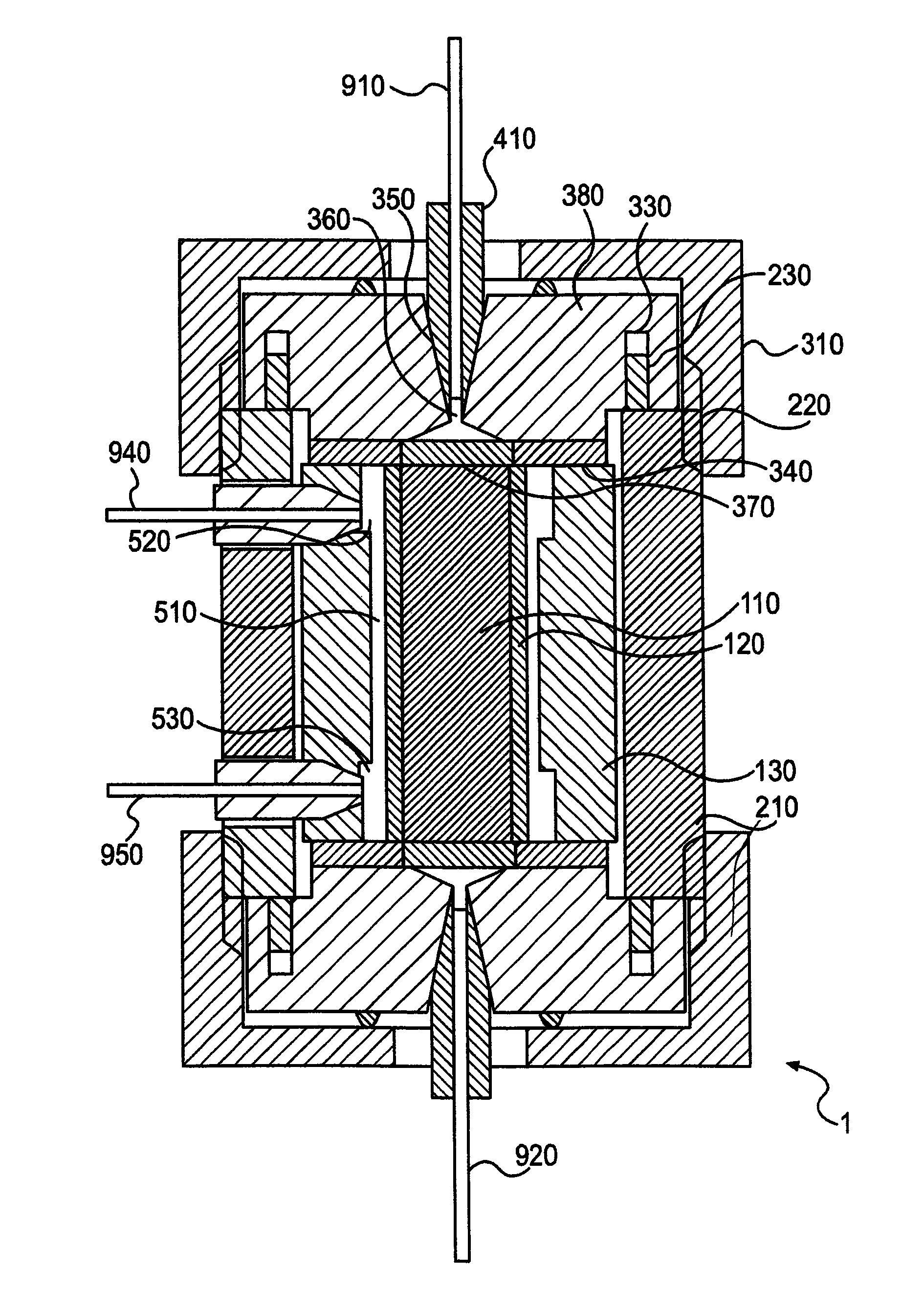
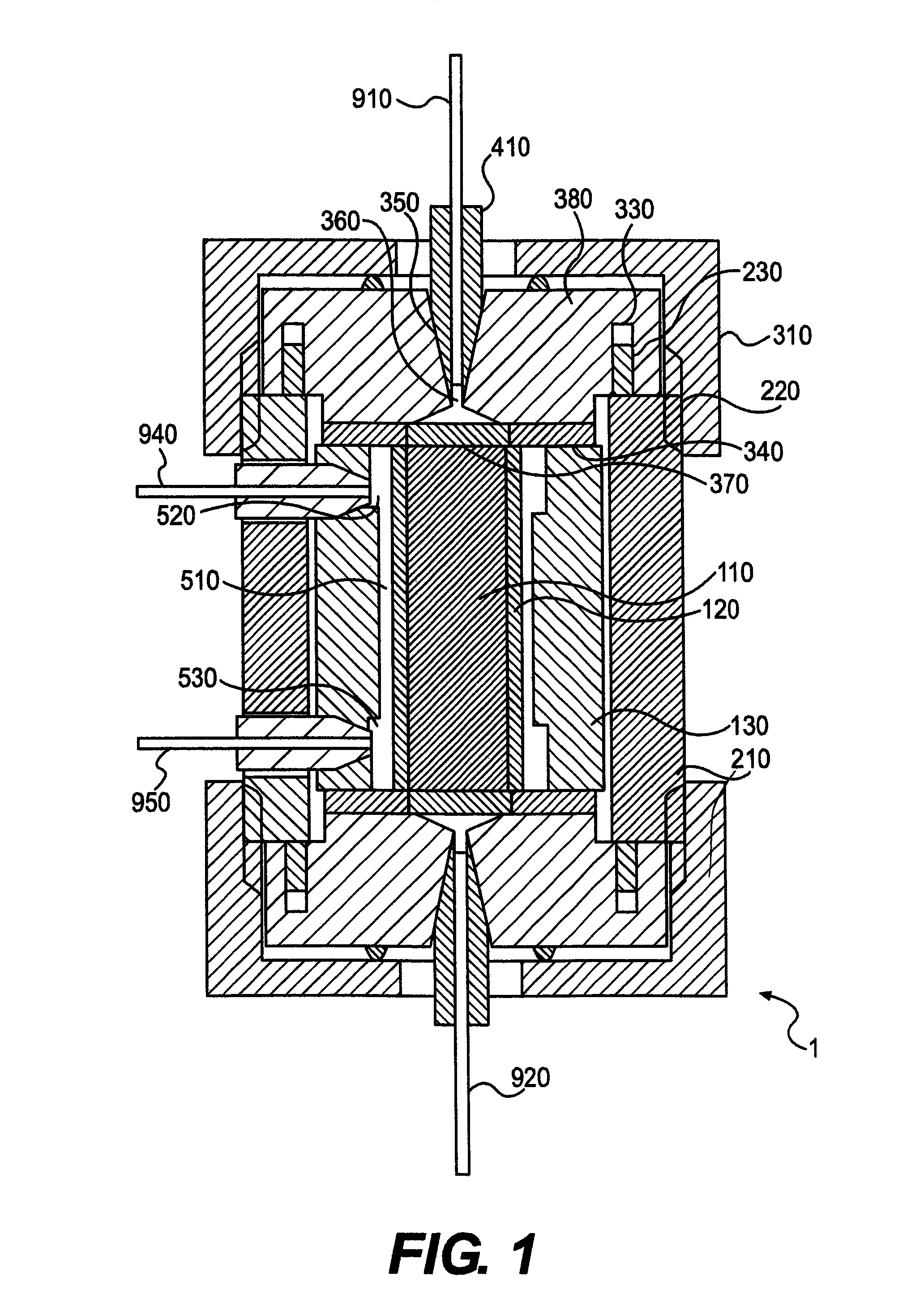
[0017]In a conventional high performance liquid chromatograph or the like, it is necessary to increase the amount of a sample transferred per unit time in order to reduce a time for analysis performed by using a particle-packed column which is used in general. To maintain the separation performance of the particle-packed column, the diameter of each of the particles to be filled needs to be reduced to increase the total area of the surfaces of the particles. Even if a particle having a diameter of about 5 μm filled in a cylindrical vessel having an inner diameter of about 4 mm, which is included in a conventional column is replaced with a particle having a diameter of about 2 μm to reduce a time for analysis to one tenth of the time, flow resistance of a sample is increased due to the reduction in the diameter of the particle. For the reason described above, it is necessary that the sample be introduced at high pressure.

[0018]Therefore, a separation column including a cylindrical po...


PUM

PropertyMeasurementUnit
pressureaaaaaaaaaa
pressureaaaaaaaaaa
diameteraaaaaaaaaa

Abstract

A separation column and a liquid chromatograph using the separation column, which are capable of carrying out a high-speed analysis under high pressure and without a reduction in separation performance of the separation column. In the separation column, a sample and a mobile phase are introduced into a packing material. The chromatograph has a covering member for covering an outer surface of the packing material and a supporting member having the packing material covered with the covering member inserted therein, wherein the level of pressure generated within a gap located between the covering member and the supporting member on the outflow side of the gap, where the fluid-flows out of the gap, is lower than that of pressure generated within the gap on the inflow side of the gap, where the fluid is introduced.

Description

BACKGROUND OF THE INVENTION[0001]1. Field of the Invention[0002]The present invention relates to a separation column for separating into components a liquid sample, which is used in a high performance liquid chromatograph (HPLC) and the like, and to a liquid chromatograph using the separation column. The invention relates more particularly to a liquid chromatograph suitable for reducing a time for analysis.[0003]2. Description of the Related Art[0004]A conventional high performance liquid chromatograph or the like includes a monolithic column having a structure in which a three-dimensional network skeleton and pores (a flow path, macro pore, and through pore) located in the skeleton are interconnected, the monolithic column being different from a particle-packed column used in general. The interconnected structure of the monolithic column makes it possible to increase the total surface area of the pores and possess large porosity without increasing resistance of the flow of a sample...

Claims


Application Information

Patent Timeline
Patent Type & Authority Patents(United States)
IPC IPC(8): G01N30/50G01N30/60B01D15/08
CPCG01N30/6047
Inventor NAGAOKA, YOSHIHIROITO, MASAHITO
Owner HITACHI HIGH-TECH CORP
Learn More