Non-destructive examination apparatus and method for guided waves

a guided wave and examination apparatus technology, applied in piezoelectric/electrostrictive transducers, instruments, specific gravity measurements, etc., can solve problems such as many challenges in the production of materials

Inactive Publication Date: 2011-05-10
FUKUOKA BROADCASTING CORPORATION
View PDF14 Cites 20 Cited by
  • Summary
  • Abstract
  • Description
  • Claims
  • Application Information

AI Technical Summary

Benefits of technology

[0009]It is therefore an objective of an aspect of the invention to provide a method for performing efficient guided wave non-destructive examination of material pieces in a cost effective and accurate manner.
[0010]It is also an objective of the invention to provide a method and apparatus to allow for synthetic manipulation of the incident angle of guided waves as they are inserted into material to be evaluated, thereby allowing scanning of the volume through the utilization of different and / or multiple modes.
[0011]It is also an objective of an aspect of the invention to provide a method of generating guided waves in material without requisite expensive and time consuming set up for conventional guided wave technologies and systems.
[0012]It is a further objective of the invention to provide a method and apparatus for investigation of rail heads, which minimizes the need for bulk wave investigation systems and instead uses guided waves for inspection. It is a still further objective of the invention to provide a guided wave inspection technique that will investigate rail webs, heads, and bases and prevent anomalies obtained during bulk wave investigations such as, for example, from rail shelling. Additionally, it may be an objective to have a sensor that is used to detect shelling.

Problems solved by technology

Ultrasonic non-destructive examination and structural health monitoring of materials produces many challenges for individuals involved with the examination or monitoring.

Method used


Image

  • Non-destructive examination apparatus and method for guided waves
  • Non-destructive examination apparatus and method for guided waves
  • Non-destructive examination apparatus and method for guided waves

Examples


Embodiment Construction

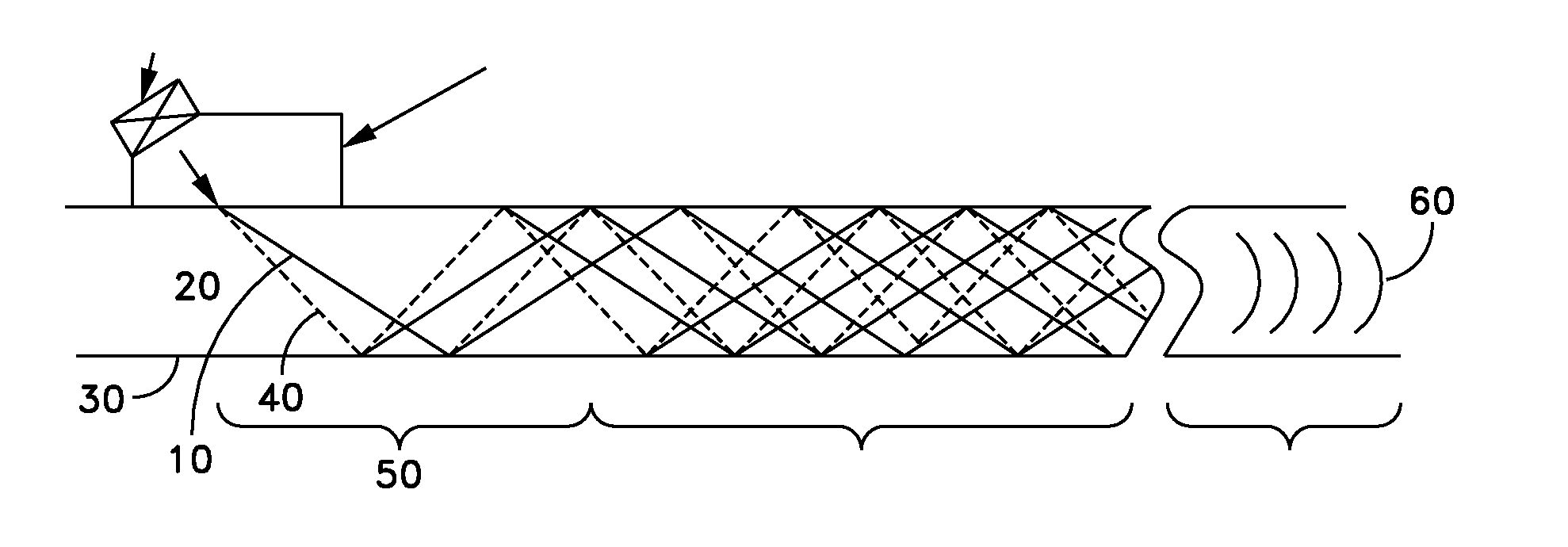
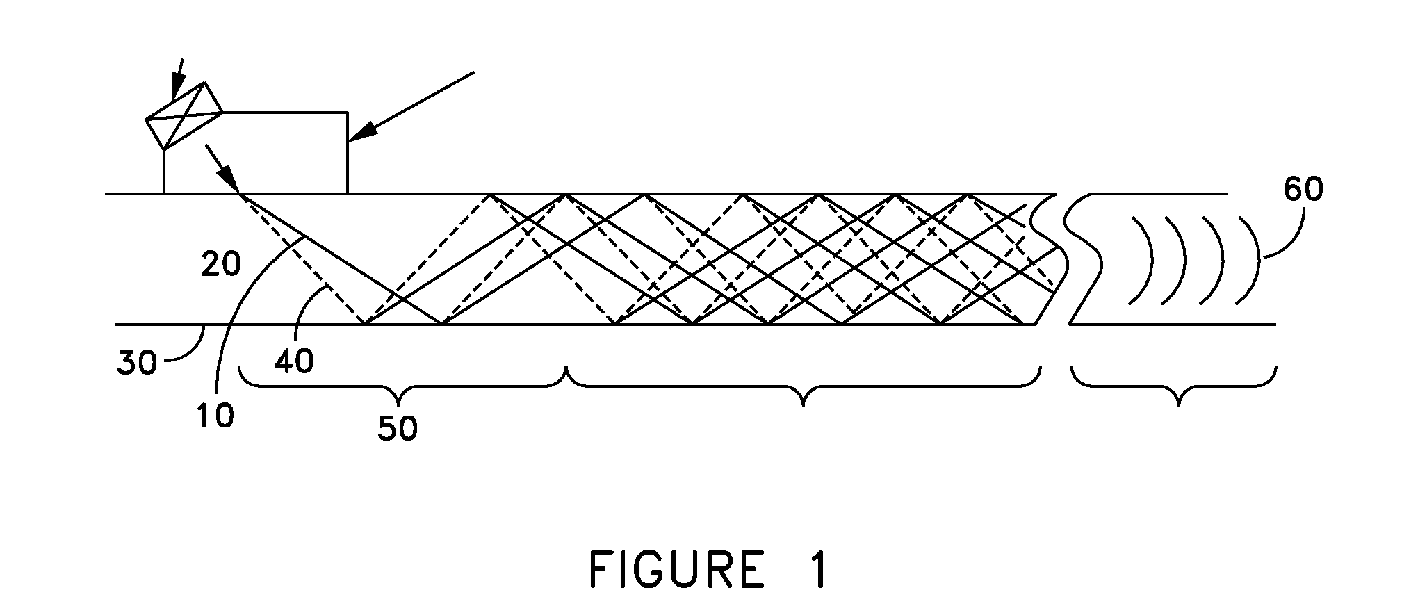
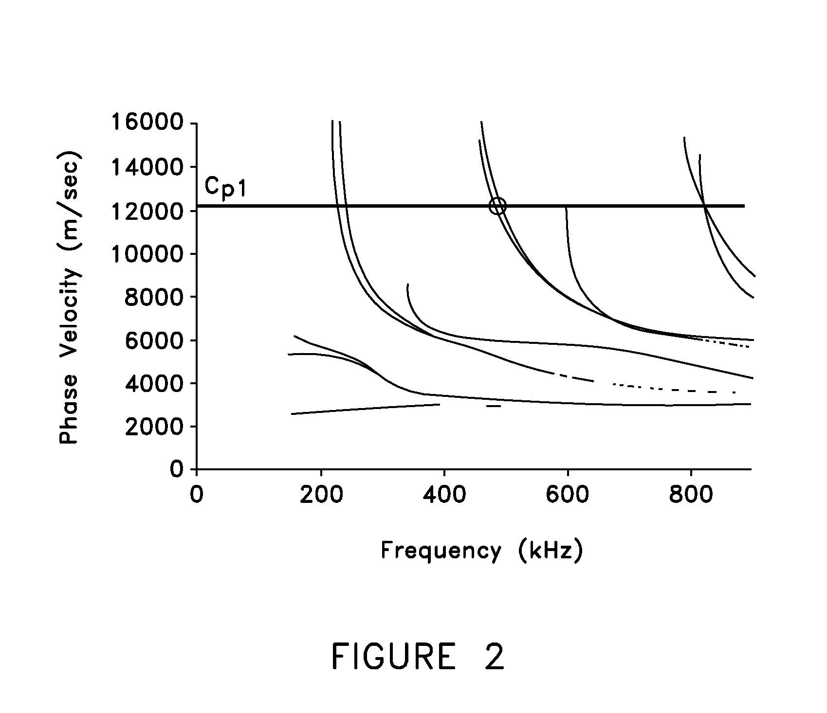
[0034]Aspects of the present invention provide for utilization of bulk wave devices and non-standard angle beam devices to create guided wave devices. In an aspect of the present invention, these guided wave devices allow for input of guided waves into materials to be evaluated. The methods and apparatus of aspects of the invention allow for accurate monitoring of these materials for defects. By providing a designer with better tools to select excitation regions within and move throughout the dispersion curve space and also to have better mode control with respect to exciting only a particular mode. By careful modification of sensor angle and frequency upon the materials, it becomes possible to create special devices that will input guided waves into material shapes such as plate, pipe and rail, as non-limiting examples.

[0035]Aspects of the invention also provide for selection of design criteria for sensor angles and sensor array time delay schedules, along with design selection of ...


PUM

PropertyMeasurementUnit
angleaaaaaaaaaa
angleaaaaaaaaaa
incident angleaaaaaaaaaa

Abstract

A method of performing a non-destructive examination of a piece of material, having the steps of providing an angle beam wedge and at least two transducers placed upon the wedge, wherein the transducers are placed in a phased array, placing the wedge upon the piece of material to be examined, producing a guided wave into the piece of material to be examined, wherein the guided wave is placed into the material through a synthetically changed incident angle, receiving the guided wave from the piece of material, and determining one of a presence of defects and lack of defects in the piece of material from the received guided wave. Transducers used may include 360 degree guided wave, radial polarized units, parallel shear units for shear horizontal activation and guided wave wheel probes.

Description

[0001]The present application claims priority under 35 U.S.C. §119(e) to U.S. Provisional Patent Application 60 / 867,468 filed on Nov. 28, 2006, the entirety of which is incorporated by reference herein.FIELD OF THE INVENTION[0002]The present invention relates to non-destructive examination and structural health monitoring. More specifically, aspects of the present invention relate to conducting non-destructive examination and / or structural health monitoring of materials through producing guided waves in the materials under examination.BACKGROUND INFORMATION[0003]Ultrasonic non-destructive examination and structural health monitoring of materials produces many challenges for individuals involved with the examination or monitoring. Two types of inspection conducted on materials include bulk wave investigation and guided wave investigation. Each of the investigation techniques has its own advantages and disadvantages.[0004]Guided wave investigation, in particular, evaluates materials b...

Claims


Application Information

Patent Timeline
Patent Type & Authority Patents(United States)
IPC IPC(8): G01N29/00
CPCG01N29/043G01N29/221G01N29/262G01N2291/2623G01N2291/0423G01N2291/0425G01N2291/0422
Inventor OWENS, STEVEN E.ROSE, JOSEPH L.ROYER, JR., ROGER L.
Owner FUKUOKA BROADCASTING CORPORATION
Why Eureka
Try Eureka