Self locking cable control apparatus

a control apparatus and self-locking technology, applied in the direction of linear movement shafts, shafts, bearings, etc., can solve the problems of too large tension force exerted by the mechanism to be controlled, too large length of travel of the controlled mechanism to be effective for use with a control cable, etc., and achieve the effect of easy manufacturing

Active Publication Date: 2011-05-10
WESCON CONTROLS
View PDF18 Cites 10 Cited by
  • Summary
  • Abstract
  • Description
  • Claims
  • Application Information

AI Technical Summary

Benefits of technology

[0008]It is thus an object of the present invention to provide a control cable assembly which is useful for manual actuation, retention and release of a control cable which is under moderate to high levels of tension, with significant cable travel, particularly in the environment of use of lawn, garden, and light utility tractors.
[0009]It is another object of the present invention to provide such a self locking control cable apparatus hereof is economical to manufacture and install in a control panel, durable in rugged conditions without requiring significant (if any) maintenance, and presents desirable ergonomic characteristics without extensive machining, a large number of parts, or complicated assembly requirements.
[0010]It is a further object of the present invention to provide a self locking control cable assembly hereof which retains the cable in an actuated condition with the control cable under tension but without the tension load being borne by a shiftable control handle of the assembly during engagement.
[0011]It is an additional object of the present invention to provide a self locking cable control apparatus which can be mounted to a control panel or the like and accommodate relatively long cable travel under moderate to high cable tension without necessitating control handles of excessive length which would be incompatible with use on a control panel.
[0012]In accordance with these and other objects evident from the following description of a preferred embodiment of the invention, a self locking cable control assembly is provided which is particularly useful for mounting to a lawn, garden, or utility tractor to control mechanisms such as a PTO where the mechanism is to be manually actuated by a control cable between an engaged and disengaged condition. The self locking cable control apparatus also avoids then need for excessive manual force to be applied to the handle, or handles of excessive length, given the relatively high tension and long cable travel. The self locking cable control assembly is preferably mounted to the frame, body part, such as a control panel, or other structure of the tractor. By shifting a control handle to from a first position to a second position, the control cable is retained in an engaged position and, correspondingly, the mechanism is engaged. However, the tension force carried by the control cable from the mechanism is borne internally by a pawl within the control assembly once the handle is shifted to the second position, and not transferred to the handle. When the user desires to return the mechanism to a disengaged condition, the handle may be easily shifted back from the second position to the first position, with a pivotal member operatively connected to but separate from the handle serving to release the pawl and thereby permit the cable to shift back under tension to the disengaged condition. Advantageously, this disengagement is effected by a controlled release of the pawl and return of the cable, to inhibit snap movements of the handle and rapid changes in tensioning to the cable during disengagement.
[0015]Thus, the present invention allows a relatively simple, easy to manufacture control assembly which is able to hold a cable in an advanced or engaged position where the tensioning force applied on the cable is relatively great, without transferring the tensioning load to the handle or driving member once shifted to the advanced position. This is advantageously accomplished through a self-locking and unlocking operation, which provides simplicity and permits control operation with only one hand. These and other advantages will be appreciated by those skilled in the art with reference to the drawings and description which follow.

Problems solved by technology

In some other applications, the force exerted by the mechanism to be controlled has been considered too great, or the length of travel of the controlled mechanism too great to be effective for use with a control cable.
For example, in some applications such as a power take-off (PTO) used in a lawn, garden or lightweight utility tractor, a lever with an overcenter retention feature has been used because the tension force exerted by the mechanism was considered too great for the use of a Bowden cable.

Method used


Image

  • Self locking cable control apparatus
  • Self locking cable control apparatus
  • Self locking cable control apparatus

Examples


Embodiment Construction

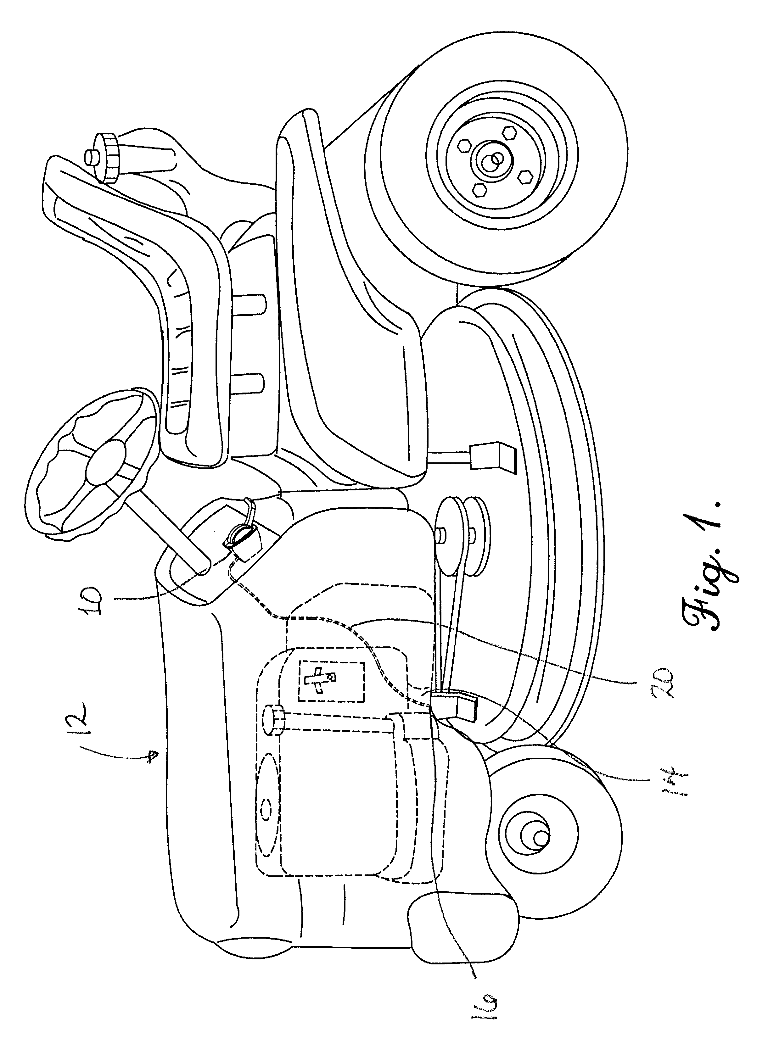
[0023]Referring now to the drawings, the cable control assembly 10 of the present invention is shown mounted on a vehicle such as a tractor 12. It is to be understood that the cable control assembly 10 is useful in connection with any other application where a controllable mechanism, such as a power-take-off unit 14 (PTO), is to be shifted between two conditions such as an engaged and a disengaged condition. The PTO 14 as illustrated is shown for operating a mower deck but could be used for other devices such as a snow thrower, rotary tiller, or the like, and the cable control assembly 10 could be used to operate a variety of other mechanisms such as a clutch, blade brake, or any other mechanism having two conditions of operation. Here, the PTO 14 includes a spring or other biasing device which applies a tension force to the remote end 16 of a cable 126 which is typically part of a Bowden cable assembly 20.

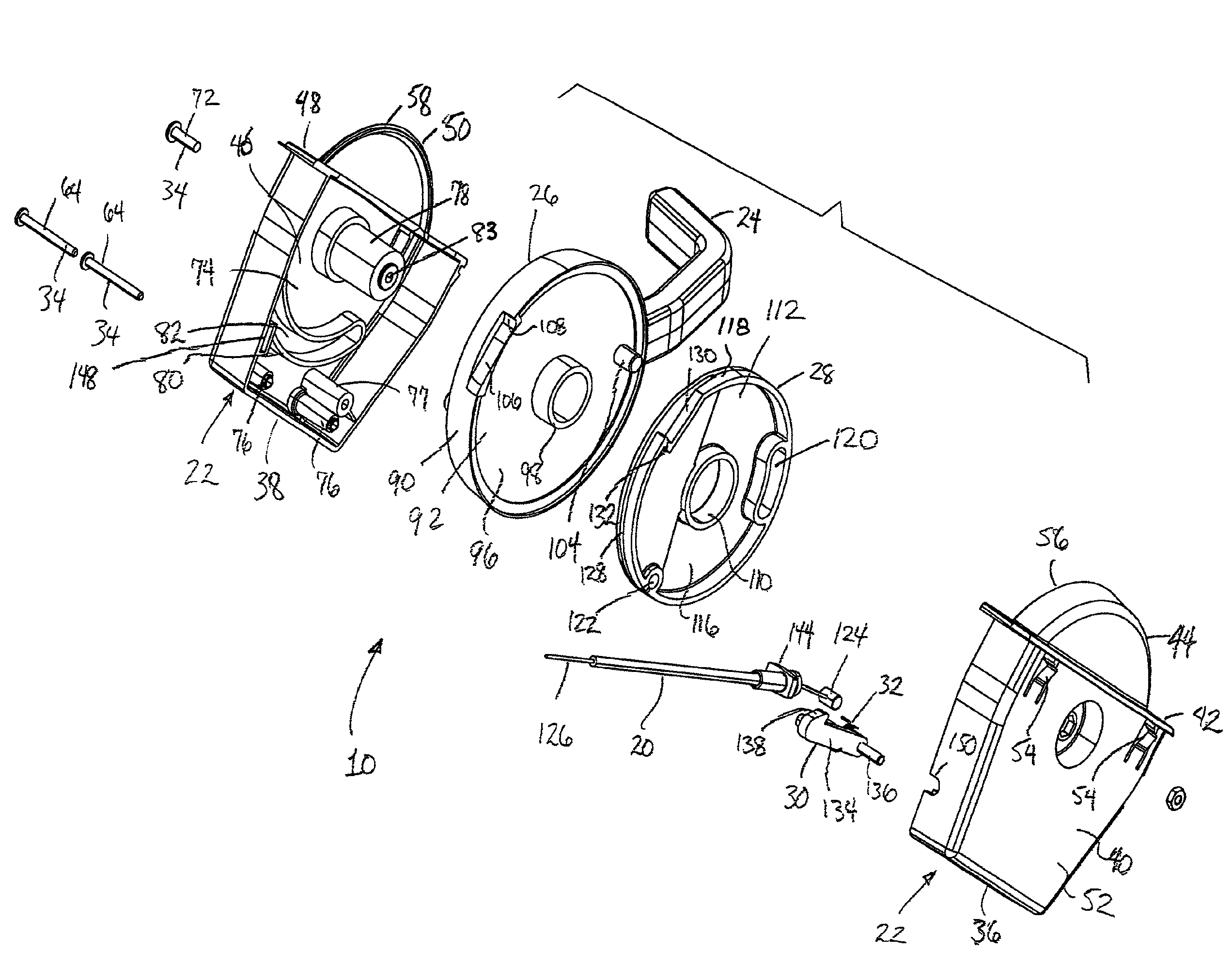
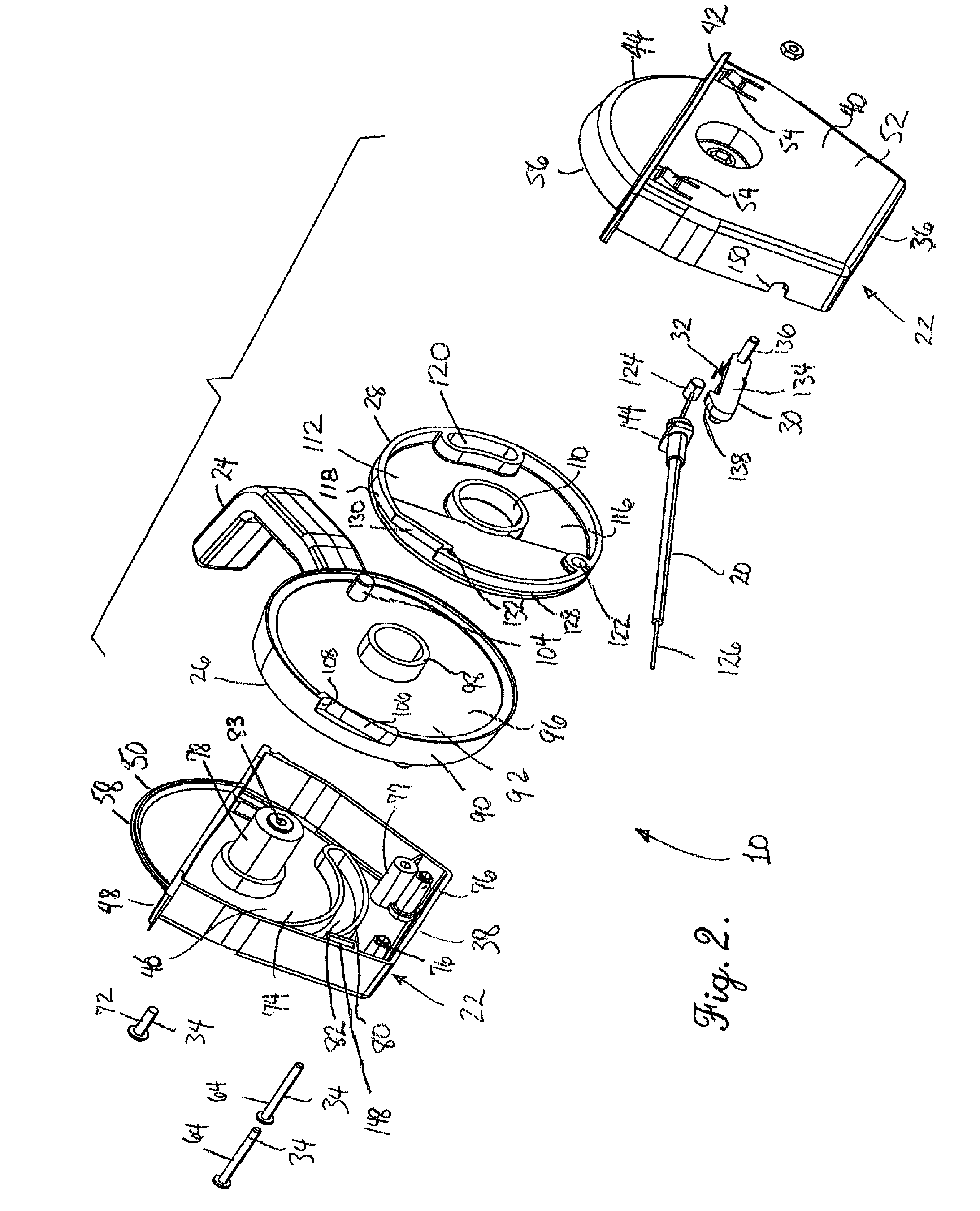
[0024]The cable control assembly 10 is shown in greater detail in FIGS. 2, 3,...


PUM


Abstract

A cable control assembly is beneficially adapted for shifting controllable mechanisms, such as a power take-off unit, between two conditions, an initial position and an actuated position. The cable control assembly preferably includes a housing, a handle extending from the housing, a driving member, a driven member, and a locking member such as a pawl. Upon shifting of the handle from an initial position to an actuated position, the driving member shifts the driven member, which is operatively coupled to the control cable. Upon reaching the actuated position, the locking member holds the driven member in the actuated position without transmitting a tensioning force applied to the control cable to the driving member. Return of the driving member in a direction toward the initial position automatically causes the locking member to move free of the driven member and enable return of the driven member and control cable to the initial position without other unlocking steps.

Description

[0001]This application claims the benefit of U.S. Provisional Application No. 60 / 786,854 filed Mar. 29, 2006.BACKGROUND OF THE INVENTION[0002]1. Field of the Invention[0003]The present invention broadly concerns a cable control apparatus for use in actuating control cables which includes a self locking structure to retain and release a control cable in and from an actuated position in response to handle movement. More particularly, it is concerned with a cable control apparatus for use with a control cable able to retain the control cable in an actuated condition notwithstanding substantial cable tension by virtue of an internal pawl arm acting on a pivoting spool.[0004]2. Description of the Prior Art[0005]Control cables are widely used in a variety of different applications for remotely controlling mechanisms such as throttles, brakes, chokes and the like. The control cable assembly is often known as a Bowden cable and includes an outer sheath and an internal control cable which is...

Claims


Application Information

Patent Timeline
Patent Type & Authority Patents(United States)
IPC IPC(8): F16C1/12
CPCF16C1/18Y10T74/2042
Inventor COX, MARVIN
Owner WESCON CONTROLS
Why Eureka
Try Eureka