Pressure sensing system for a planter

a planter and pressure sensing technology, applied in the field of pressure sensing system for planters, can solve the problems of relative high cost and the necessity of wiring harnesses

Active Publication Date: 2011-05-10
DEERE & CO
View PDF8 Cites 108 Cited by
  • Summary
  • Abstract
  • Description
  • Claims
  • Application Information

AI Technical Summary

Problems solved by technology

The disadvantage of this load sensing pin it is the relatively high cost and necessity of a wiring harness.

Method used


Image

  • Pressure sensing system for a planter
  • Pressure sensing system for a planter
  • Pressure sensing system for a planter

Examples


Embodiment Construction

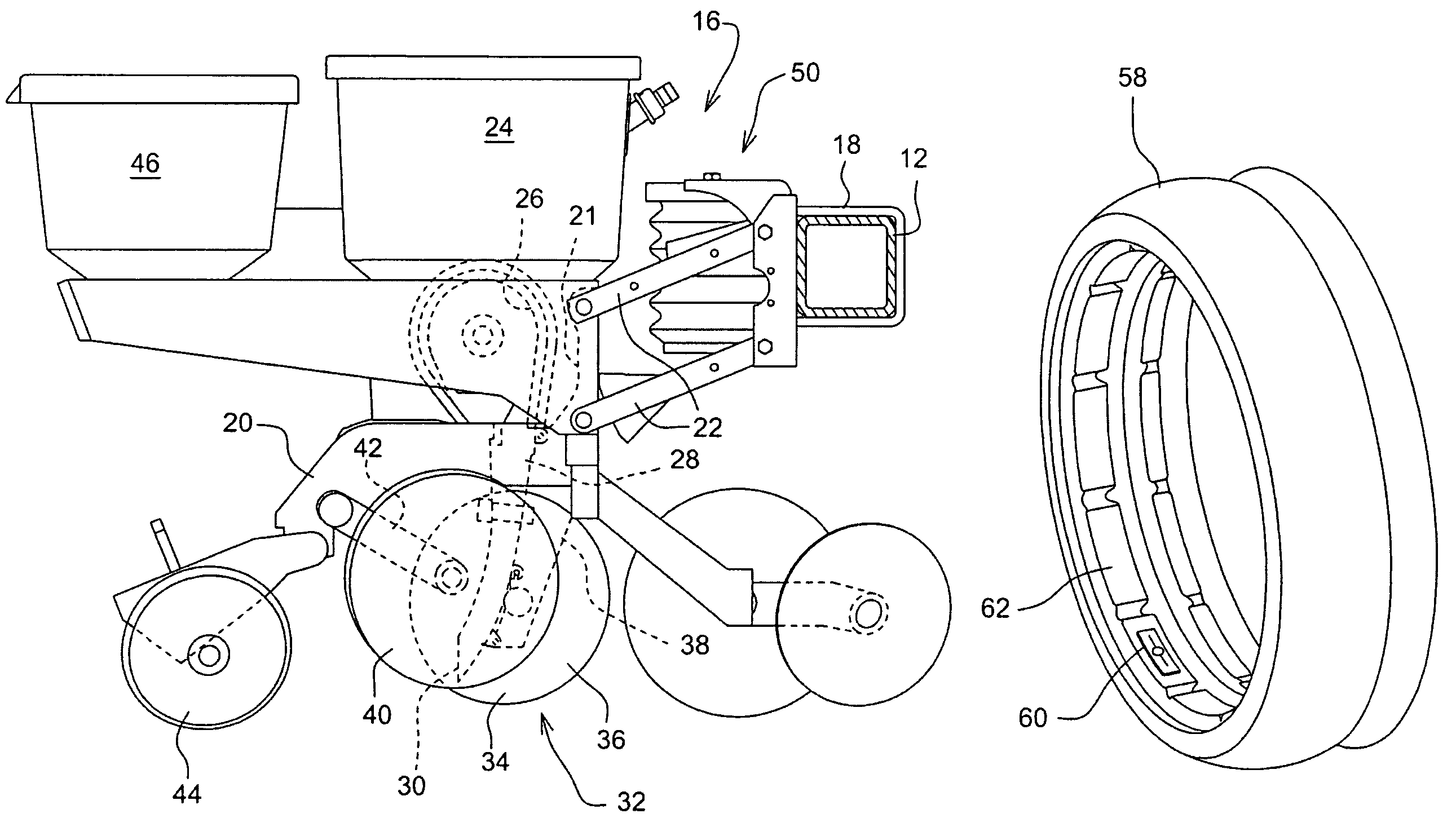
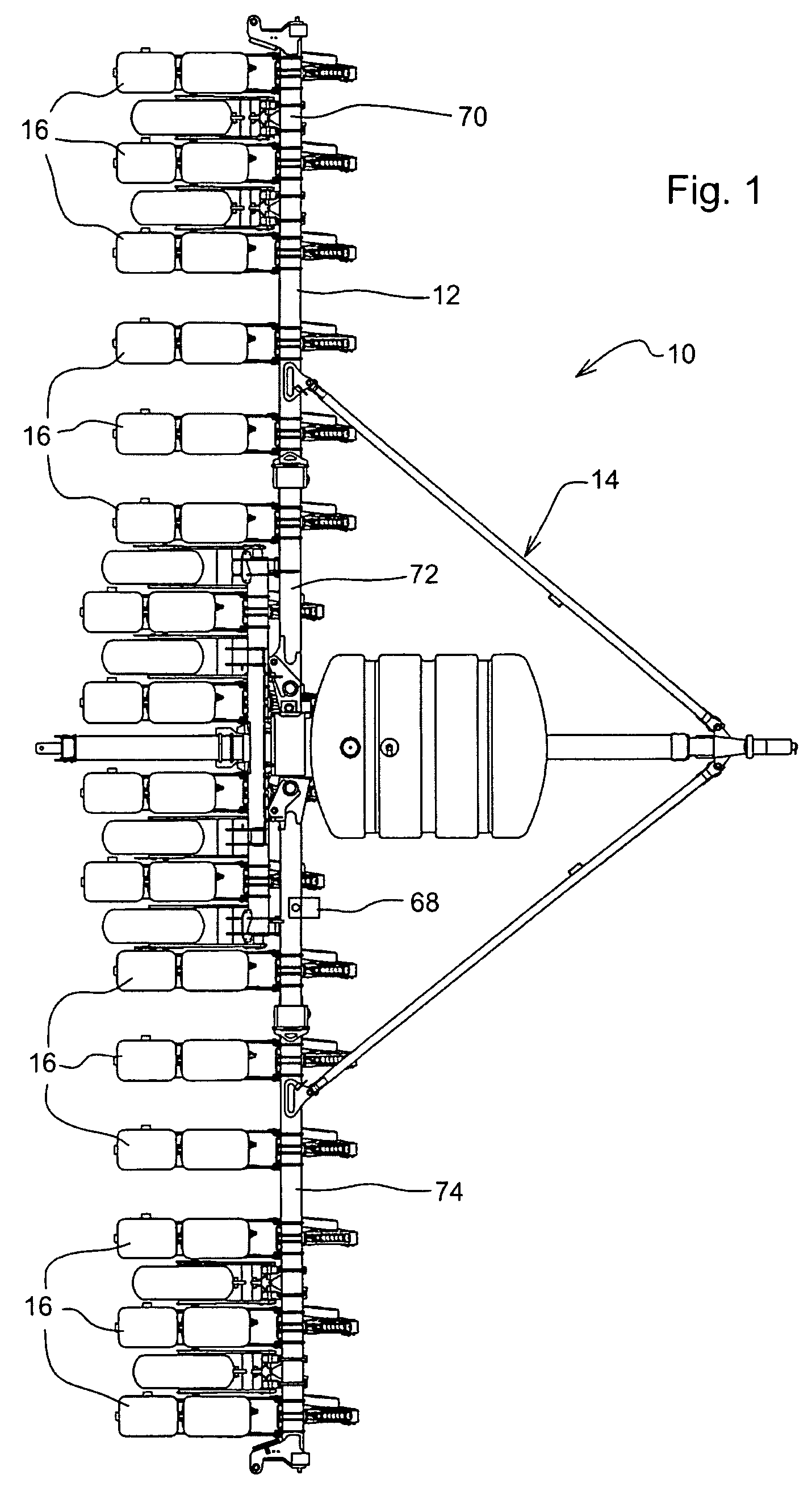
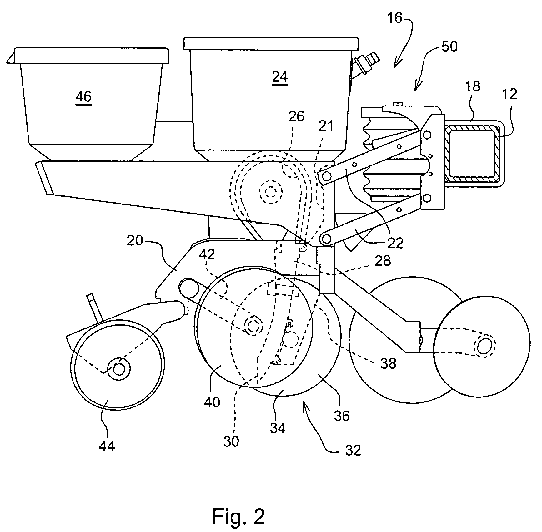
[0009]With reference to FIG. 1, an example planter 10 is shown containing the down force pressure sensor system of the present invention. Planter 10 includes a tool bar 12 as part of a planter frame 14. Mounted to the tool bar are multiple planting row units 16. Row units 16 are typically identical for a given planter but need not be identical. A row unit 16 is shown in greater detail in FIG. 2. The row unit 16 is mounted to the tool bar 12 by U-bolts 18. The row unit 16 is provided with a central frame member 20 having a pair of upwardly extending arms 21 at the forward end thereof. The arms 21 connect to a parallelogram linkage 22 for mounting the row unit 16 to the tool bar 12 for up and down relative movement between the unit 16 and toolbar 12 in a known manner. Seed is stored in seed hopper 24 and provided to seed meter 26. From the seed meter 26 the seed is dropped through a seed tube 28. The lower end 30 of the seed tube is positioned just above a seed trench formed by a tren...


PUM


Abstract

A pressure sensing system for a seeding machine such as a planter to measure the down force on a planter row unit uses a wireless pressure sensor embedded in a load carrying wheel of the row unit. In a preferred embodiment, the pressure sensor is a passive piezoelectric pressure sensor that is a transmitter only, transmitting both pressure and RFID the information that identifies the particular sensor. Multiple sensors may be employed in each wheel and sensors may be employed in more than one wheel of the row unit, such as the gauge wheels on opposite sides of the trench opening disks. The sensors may be made of a PVDF, a known piezoelectric material. A wireless receiver is located on the planter frame or could be located elsewhere to receive the signals from the pressure sensor. A controller determines from the signal, any change in down force and commands the change to a down force generator on the row unit.

Description

BACKGROUND OF THE INVENTION[0001]When planting with a conventional row crop planter having a plurality of row units mounted on a toolbar, it is necessary to provided a sufficient a down force on each row unit to ensure that the seed trench opener fully penetrates into the soil. To provide the necessary down force, each row unit is typically provided with a down force generator at the linkage mounting in the row unit to the toolbar. The down force generator may be a mechanical, spring type, generator that produces a fixed down force or which may provide for adjustment to vary the down force. Pneumatic or hydraulic down force generator's can also be used which facilitate electronic control of the magnitude of the down force. Proper down force control is also essential to provide the proper amount of soil compaction in the side walls of the seed trench.[0002]In order to control the magnitude of the down force, it is necessary to measure the magnitude of the down force in real time duri...

Claims


Application Information

Patent Timeline
Patent Type & Authority Patents(United States)
IPC IPC(8): A01C5/00A01C13/00A01C15/00B60C23/00B60C23/02
CPCA01C7/205A01C5/068Y10S111/903
Inventor LIU, JAMES Z.
Owner DEERE & CO
Why Eureka
Try Eureka