Grounding electrical connector

a grounding and electrical connector technology, applied in the direction of coupling devices, two-part coupling devices, electrical apparatus, etc., can solve the problems of poor contact between the connector main body, and the coaxial cable connector has some defects. , to achieve the effect of good signal transmission quality and good electrical performan

Active Publication Date: 2011-05-10
EZCONN
View PDF21 Cites 36 Cited by
  • Summary
  • Abstract
  • Description
  • Claims
  • Application Information

AI Technical Summary

Benefits of technology

[0008]A primary object of the present invention is to provide a grounding electrical connector includes a conductive grounding spring mounted in an inner sleeve. An inner threaded section of a nut of the grounding

Problems solved by technology

The conventional coaxial cable connector has some defects.
There is an inherent problem existing in the connection between the F-type connector main body 10 and the threaded interface connector 15.
The gap

Method used


Image

  • Grounding electrical connector
  • Grounding electrical connector
  • Grounding electrical connector

Examples


Embodiment Construction

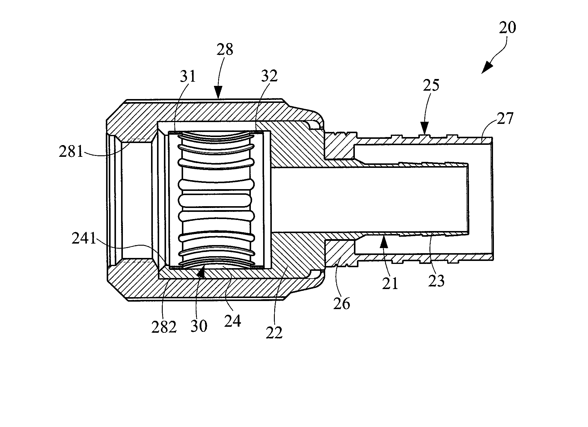
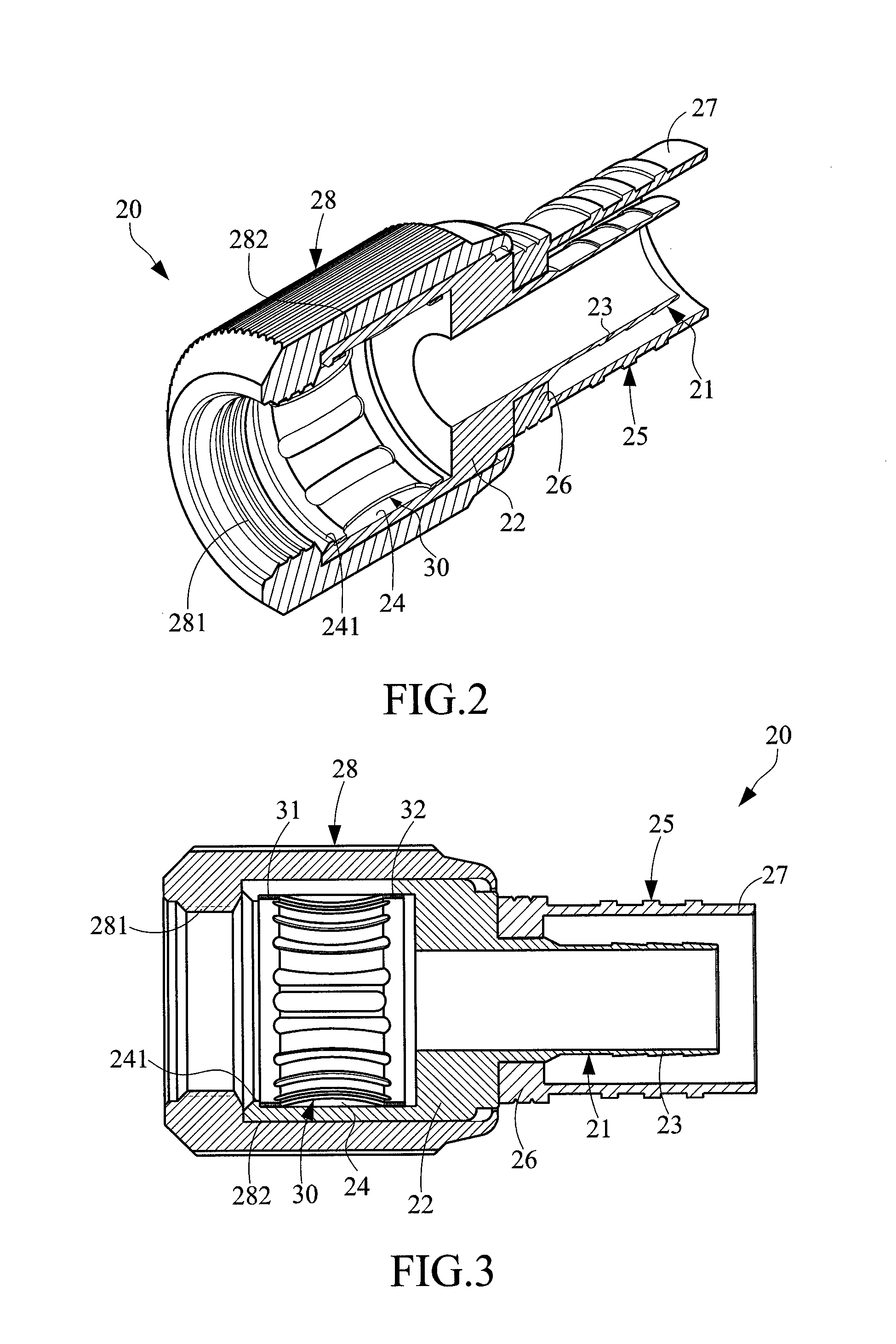
[0020]Please refer to FIGS. 2 and 3, in which FIG. 2 is a perspective sectional view of the grounding electrical connector of the present invention and FIG. 3 is a sectional view of the grounding electrical connector of the present invention. The grounding electrical connector 20 includes an inner sleeve 21, an outer sleeve 25 and a conductive grounding spring 30. A front end of the inner sleeve 21 has an outer flange 22. A rear end of the inner sleeve 21 has a rearward extending section 23. The rearward extending section 23 has an outer diameter and a wall thickness smaller than those of the outer flange 22. An annular groove 24 is formed on an inner circumference of the outer flange 22 for receiving the conductive grounding spring 30 therein. A front end of the annular groove 24 has an annular stop section 241 for locating the conductive grounding spring 30 in the annular groove 24. A front end of the outer sleeve 25 has an inner flange 26 embracing the inner sleeve 21. A rear end...


PUM


Abstract

A grounding electrical connector includes: an inner sleeve, a front end of the inner sleeve having an outer flange, an annular groove being formed on an inner circumference of the outer flange; an outer sleeve coaxially positioned around the inner sleeve; a nut formed with an inner threaded section for locking with a threaded interface connector of an electronic device, the nut further having a receptacle for receiving the outer flange of the inner sleeve therein; and a conductive grounding spring mounted in the annular groove of the inner sleeve and having multiple inner resilient concave sections. When the threaded section of the nut is screwed onto the threaded interface connector of the electronic device, the inner resilient concave sections of the conductive grounding spring are mechanically and electrically connected with a circumference of the threaded interface connector.

Description

BACKGROUND OF THE INVENTION[0001]1. Field of the Invention[0002]The present invention relates generally to a connector, and more particularly to a grounding electrical connector with a good grounding effect.[0003]2. Description of the Related Art[0004]It is well known that a coaxial cable connector is connectable with a threaded interface connector of an electronic device to electrically connect a coaxial cable with the electronic device.[0005]The conventional coaxial cable connector has some defects. For example, the main body of the coaxial cable connector must be connected with the interface connector with a good grounding connection. This is involved in whether the coaxial cable connector is well grounded. FIG. 1 shows an F-type connector as atypical example of the conventional connector. The F-type connector includes a connector main body 10. The connector main body 10 includes an outer sleeve 11, an inner sleeve 12 coaxially positioned in the outer sleeve 11 and a nut 13 rotat...

Claims


Application Information

Patent Timeline
IPC IPC(8): H01R9/05
CPCH01R13/187H01R24/40H01R2103/00
Inventor HSIEH, CHI-FENG
Owner EZCONN
Why Eureka
Try Eureka