
Connector with a tubular shield with double left and right sides formed from a single metal plate

a tubular shield and connector technology, applied in the direction of two-part coupling devices, coupling device connections, electrical apparatus, etc., can solve the problems of increased production costs, increased assembling manpower, and large outer shape of the connector, so as to improve enhance the strength of the metal plate parts, and ensure the effect of shielding performan

Inactive Publication Date: 2011-05-10
HOSIDEN CORP
View PDF12 Cites 12 Cited by
  • Summary
  • Abstract
  • Description
  • Claims
  • Application Information

AI Technical Summary

Benefits of technology

[0019]When, as in the connector of the invention, the shield cover 30 is configured so that the right and left side plates of the tubular portion 32 are disposed inward and outward or doubly, the right and left mounting terminals 33 which are downward projected respectively from portions in rear of the front end opening of the tubular portion 32 are disposed by the extended portions of the outer right and left side plates 42, 43 of the tubular portion, and the elastic piece which is inward extended from the front end face of at least one of the right and left mounting terminals 33 is configured as the second contact piece (a contact piece for the case of the apparatus) 35, the bend radius of the basal end portion and overall length of the second contact piece 35 can be sufficiently ensured. Although the second contact piece 35 is formed as an inward-directed piece which does not cause the outer shape of the connector to be enlarged, adequate elasticity is easily obtained, and the shield cover 30 is contacted with the case 200 of the apparatus through the second contact piece 35. Therefore, a stable and sure grounding connection can be obtained.
[0021]When the configuration is employed, a seam joint 50 between the right and left half bottom plates 48, 49 is formed in the middle portion of the bottom face of the tubular portion 32. However, the outer right and left side plates 42, 43 of the tubular portion 32 are engaged with the circuit board 100 by the right and left mounting terminals 33. When the connector is pryed when the counter connector P is inserted, therefore, the joint 50 is opened, and the tubular shape of the tubular portion 32 is deformed, whereby fitting and contact failures, or the like can be prevented from occurring.
[0023]When the configuration is employed, the right and left bent portions 54, 55 play a role of ribs which enhance the strengths of the metal plate portions forming the outer right and left side plates 42, 43 and the right and left mounting terminals 33, and the tubular shape of the tubular portion 32 is formed by vertically combining the U-like shape which is configured by the top plate 41 and the outer right and left side plates 42, 43, and which is downward opened, with that which is configured by the right and left half bottom plates 48, 49 and the inner right and left side plates 46, 47, and which is upward opened, so as to cause the inner and outer right and left side plates 46, 42, 4743 to overlap each other. The right and left bent portions 54, 55 enable the upward-opened U-like shape to be embraced in the downward-opened U-like shape, so that the strength against prying caused by the counter connector P can be further enhanced.
[0024]According to the invention, it is possible to provide a connector in which a highly reliable shielding performance can be realized while reducing the production cost and the size.

Problems solved by technology

Consequently, there arises a problem in that the assembling manpower is correspondingly increased and the production cost is raised.
Furthermore, there is a problem in that the outer shape of the connector becomes large.
Consequently, the assembling manpower is correspondingly increased and the production cost is raised.
Similarly with the case of the connector disclosed in, for example, Patent Literature 2, there is a problem in that the outer shape of the connector becomes large.
However, the configuration cannot be employed in a connector in which only one plug insertion port is formed by one shield cover as in, for example, the connector disclosed in Patent Literature 1.
In a connector in which only one plug insertion port is formed by one shield cover, therefore, only a contact piece which is outward extended from the opening edge of the plug insertion port can be disposed (a contact piece which is inward extended interferes with an inserted plug), and hence there is a problem in that the outer shape of the connector is inevitably large.
Therefore, the bend radius of the contact piece from the opening edge of the plug insertion port cannot be set to be large, the contact piece is restricted to have a short length, and a large stress is produced in the contact piece, thereby causing problems in that breakage or plastic deformation easily occurs, and that adequate elasticity is hardly obtained.
When the gap between the opening edge of the plug insertion port and the case is enlarged, the shielding performance is reduced.
In a conventional connector which is so-called EMI shielded connector, as described above, it is difficult to realize a highly reliable shielding performance while reducing the production cost and the size.

Method used


Image

  • Connector with a tubular shield with double left and right sides formed from a single metal plate
  • Connector with a tubular shield with double left and right sides formed from a single metal plate
  • Connector with a tubular shield with double left and right sides formed from a single metal plate

Examples


Embodiment Construction

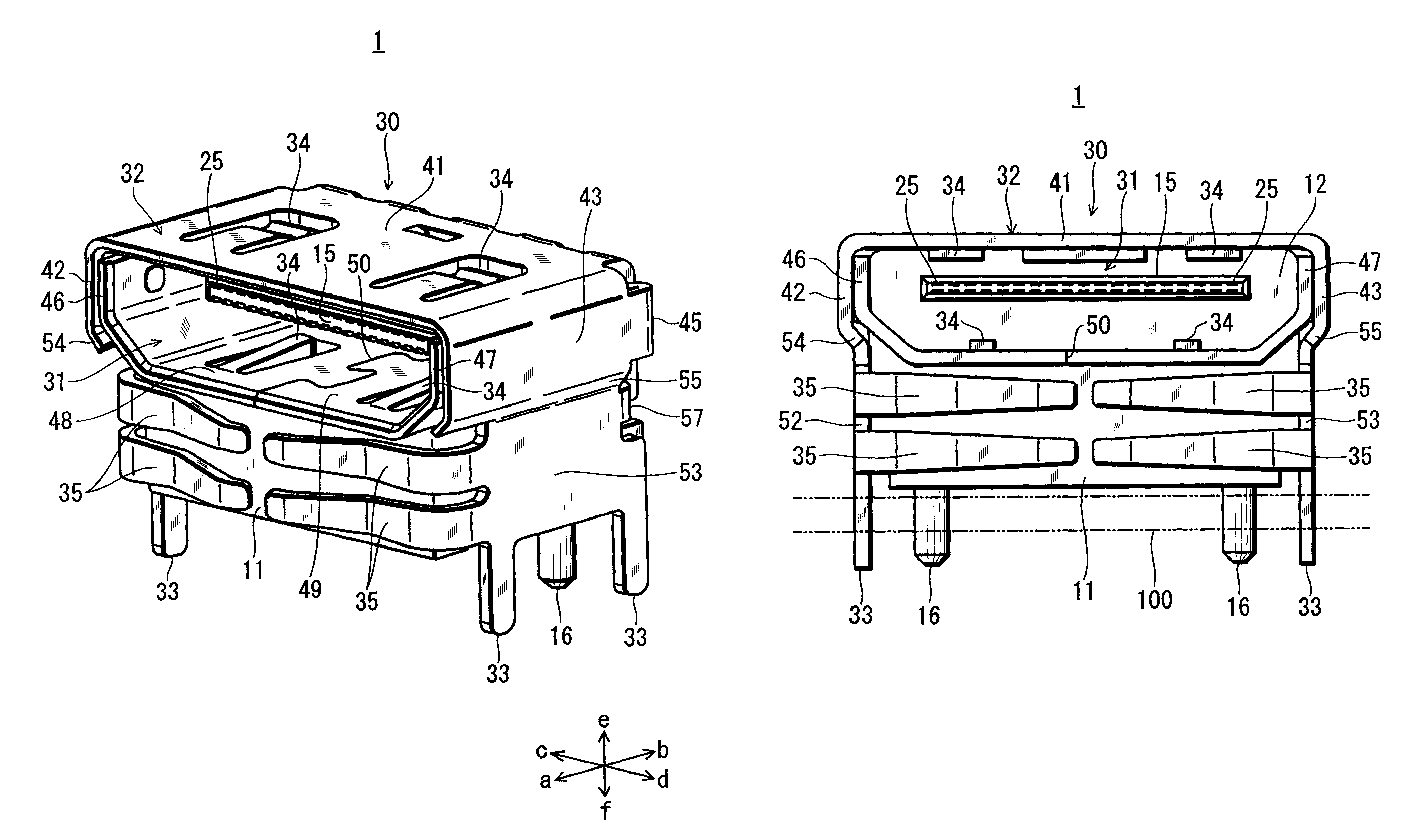
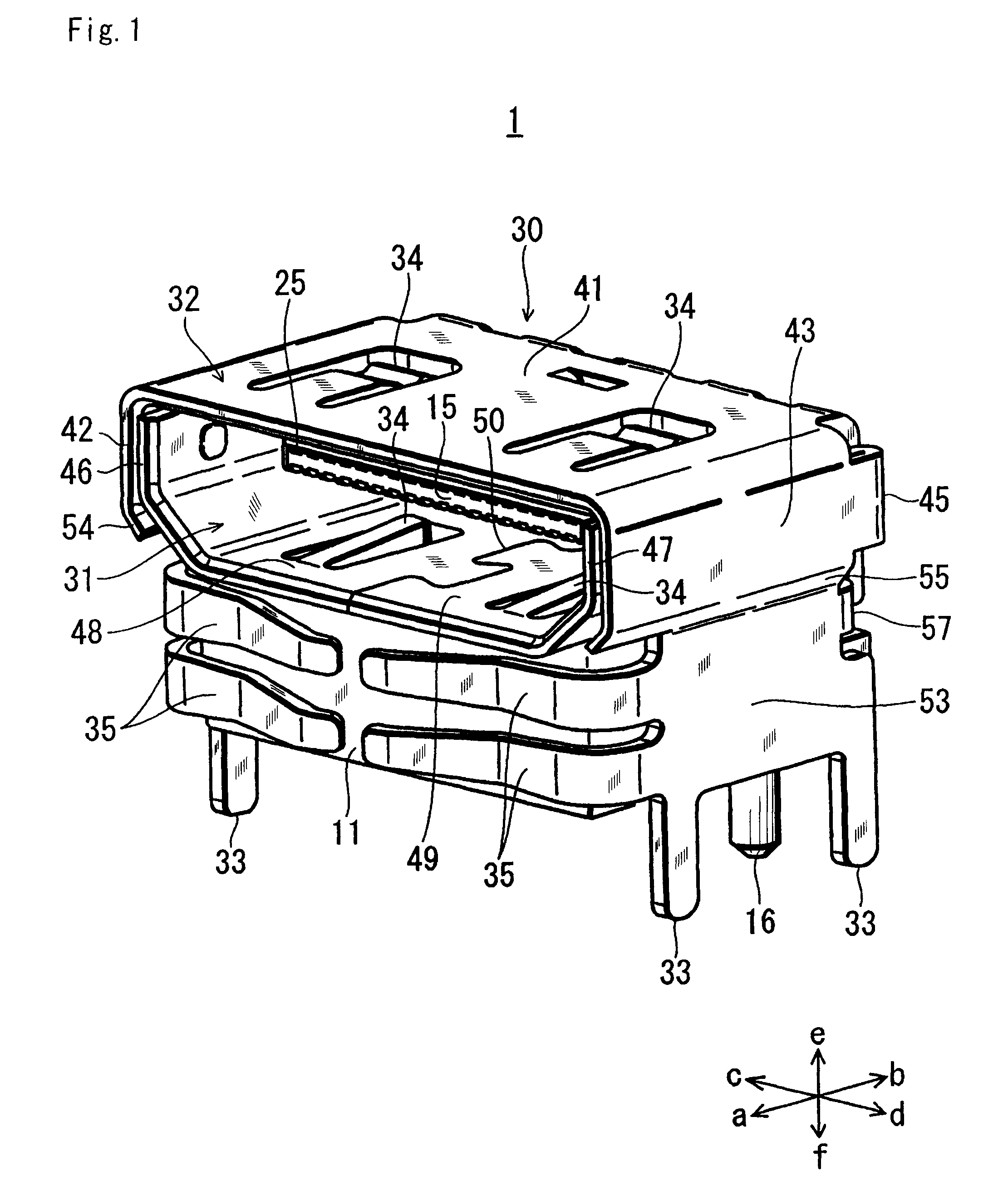
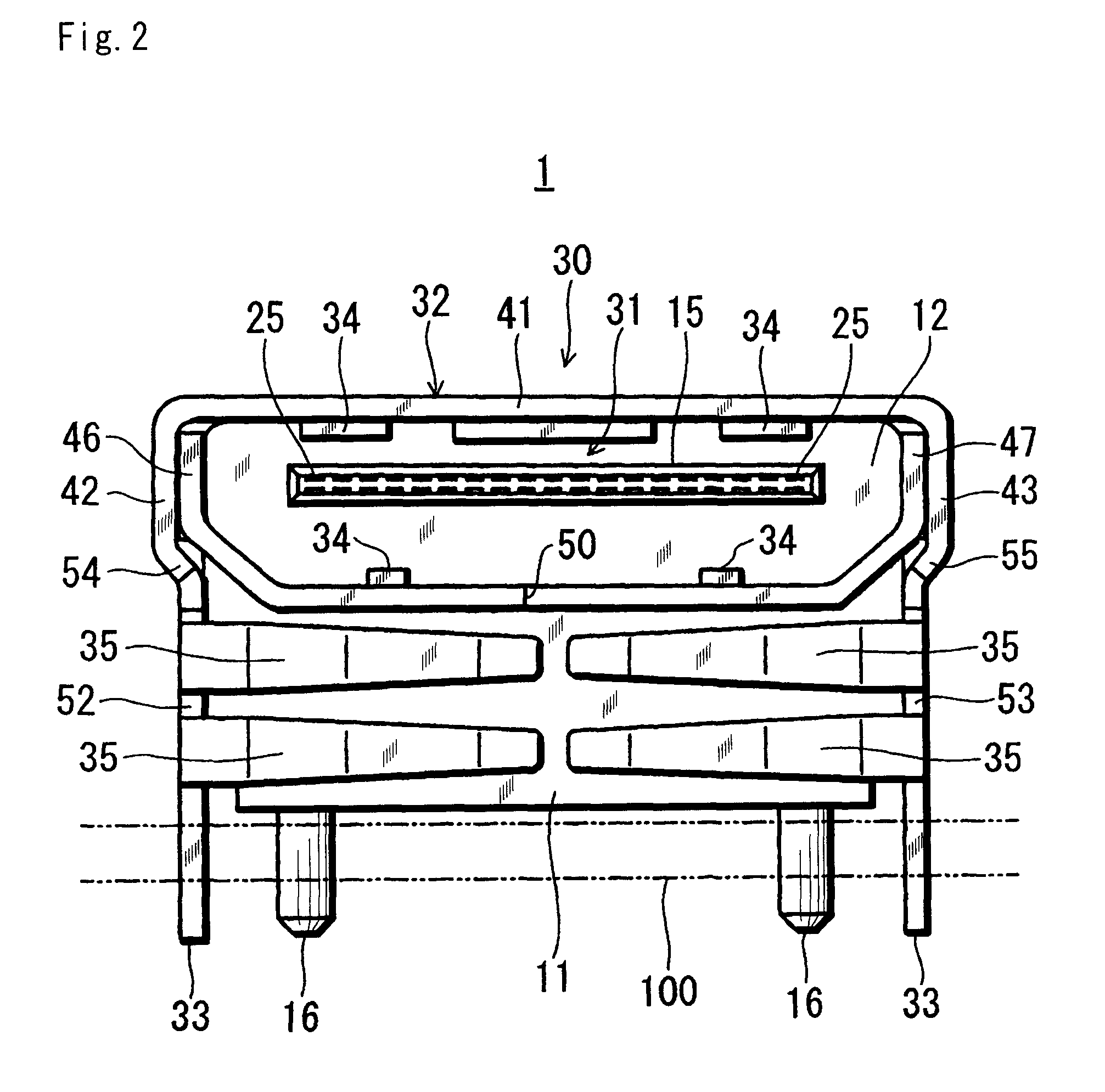
[0030]Hereinafter, an embodiment of the invention will be described with reference to the drawings. In the following description, it is assumed that the directions of arrows a-b in FIG. 1 coincide with the front and rear directions (the depth direction, the insertion / extraction directions of the counter connector) of the connector, the directions of arrows c-d coincide with the right and left directions (width direction) of the connector, and the directions of arrows e-f coincide with the upper and lower directions (height direction) of the connector.

[0031]The connector 1 of the embodiment shown in FIGS. 1 to 4 is an apparatus-side connector (socket) which is to be used in, for example, a PC, a peripheral apparatus thereof, or an AV apparatus while being mounted on an edge portion of a printed circuit board 100. The counter connector P for the connector 1 is a plug P such as a cable-side connector to be attached to an end of a connection cable between apparatuses, or a memory-side c...


PUM


Abstract

The invention provides a connector wherein a highly reliable shielding performance can be realized while reducing the production cost and the size. A connector includes a shield cover configured by one metal plate. In the shield cover, a tubular portion which forms a fitting portion for a plug, mounting terminals for a printed circuit board, first contact pieces for a shield member of the plug, and second contact pieces for a case of an apparatus are integrally disposed. In the tubular portion, inner and outer double right and left side plates are disposed. The mounting terminals are configured by right and left extended portions downward projected from portions of the outer right and left side plates in rear of a front end opening of the tubular portion. The second contact pieces are configured by elastic pieces inward extended from the front end faces of the mounting terminals.

Description

TECHNICAL FIELD[0001]The present invention relates to a connector which is to be mounted on a printed circuit board, and more particularly to a connector which includes a shield cover for electrically connecting a shield member of a plug that is a counter connector, to a printed circuit board, and which is a so-called EMI (electromagnetic interference) shielded connector.BACKGROUND OF THE INVENTION[0002]In such a connector, usually, a shield cover is contacted with a case of an apparatus in a plug insertion port to establish a grounding connection, thereby enhancing the shielding performance. For example, Patent Literatures 1 to 6 listed below disclose a connector in which, in addition to mounting terminals for a printed circuit board and a contact piece for a shield member of a plug, a contact piece for a case is disposed in a plug insertion port of a shield cover.[0003][Patent Literature 1] Japanese Patent Application Laying-Open No. 10-64636[0004][Patent Literature 2] Japanese Pa...

Claims


Application Information

Patent Timeline
IPC IPC(8): H01R13/648
CPCH01R12/724H01R13/65802H01R13/6582H01R24/60H01R13/6594H01R2201/06H01R43/16
Inventor NAGATA, TAKAYUKI
Owner HOSIDEN CORP
Learn More