Method and group for the compression molding of preforms for containers in polymeric material

a polymeric material and container technology, applied in the field of compression molding of semi-finished preforms, can solve the problems of compensating the inexactness of the mass of the metered body, breaking or to unacceptable damage of the neck parts themselves, and reducing so as to increase the thickness of the hollow body, the effect of less inner tension and less internal tension

Inactive Publication Date: 2011-05-10
SACMI COOP MECCANICI IMOLA SOC COOP A R L
View PDF10 Cites 28 Cited by
  • Summary
  • Abstract
  • Description
  • Claims
  • Application Information

AI Technical Summary

Benefits of technology

[0009]Another object of the invention is to improve at the same time the thermal exchange between the mold and preform which takes place during the molding and the subsequent solidification of the preform itself, in order to render more rapid such solidification step.

Problems solved by technology

A technical problem, present in the described technology and connected with said molds, arises from the fact that, in the metering of the body of polymeric material (metering) to be inserted into the matrix (typically through the separation of the body from a continuous and unshaped mass supplied by an extruder means), one inevitably obtains (small) differences in value with respect to the pre-established value, while the volume of the (closed) chamber of the mold, which must be completely and exactly filled with polymeric material to form the preform, is instead constant for each mold; there exists therefore the technical problem of compensating the inexactness of the mass of the metered body with respect to the reference value.
This solution, while having the merit of transferring the mass error into a formal element which disturbs neither the functionality nor the external aspect of the bottle, presents nevertheless considerable disadvantages.
This involves the rising of inner tensions in the zone where the error compensation takes place, which, when the neck subsequently undergoes mechanical stress, for example in the capping step of the bottle, may lead to the breaking or to unacceptable damage of the neck parts themselves.
Moreover, for example, in the case in which, as the Japanese document foresees, said error transferring is localised in a zone where a circular groove is present on the collar of the neck, it occurs that when the collar itself slides along appropriate transfer guides, such groove causes undesirable friction and moreover acts as a receptacle for dirt.

Method used


Image

  • Method and group for the compression molding of preforms for containers in polymeric material
  • Method and group for the compression molding of preforms for containers in polymeric material
  • Method and group for the compression molding of preforms for containers in polymeric material

Examples


first embodiment

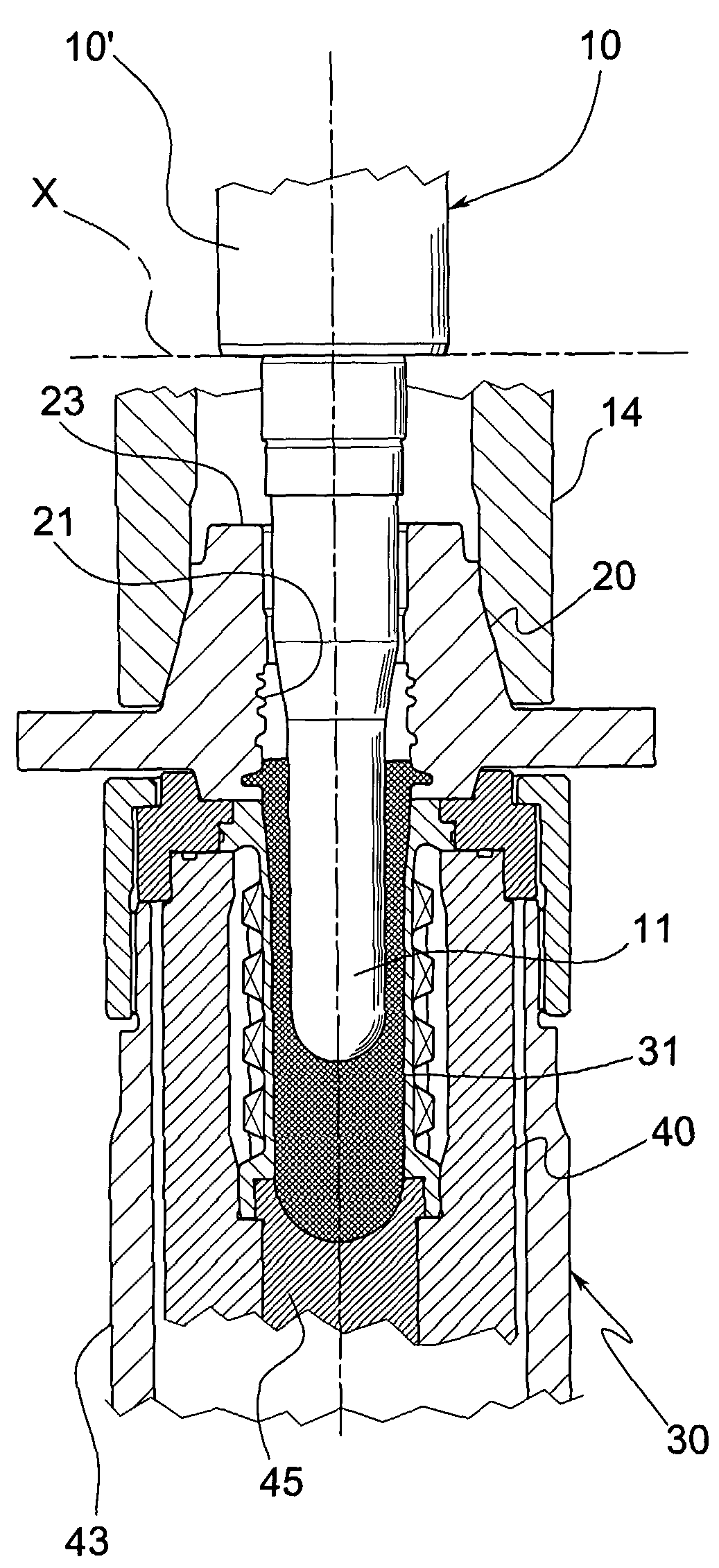
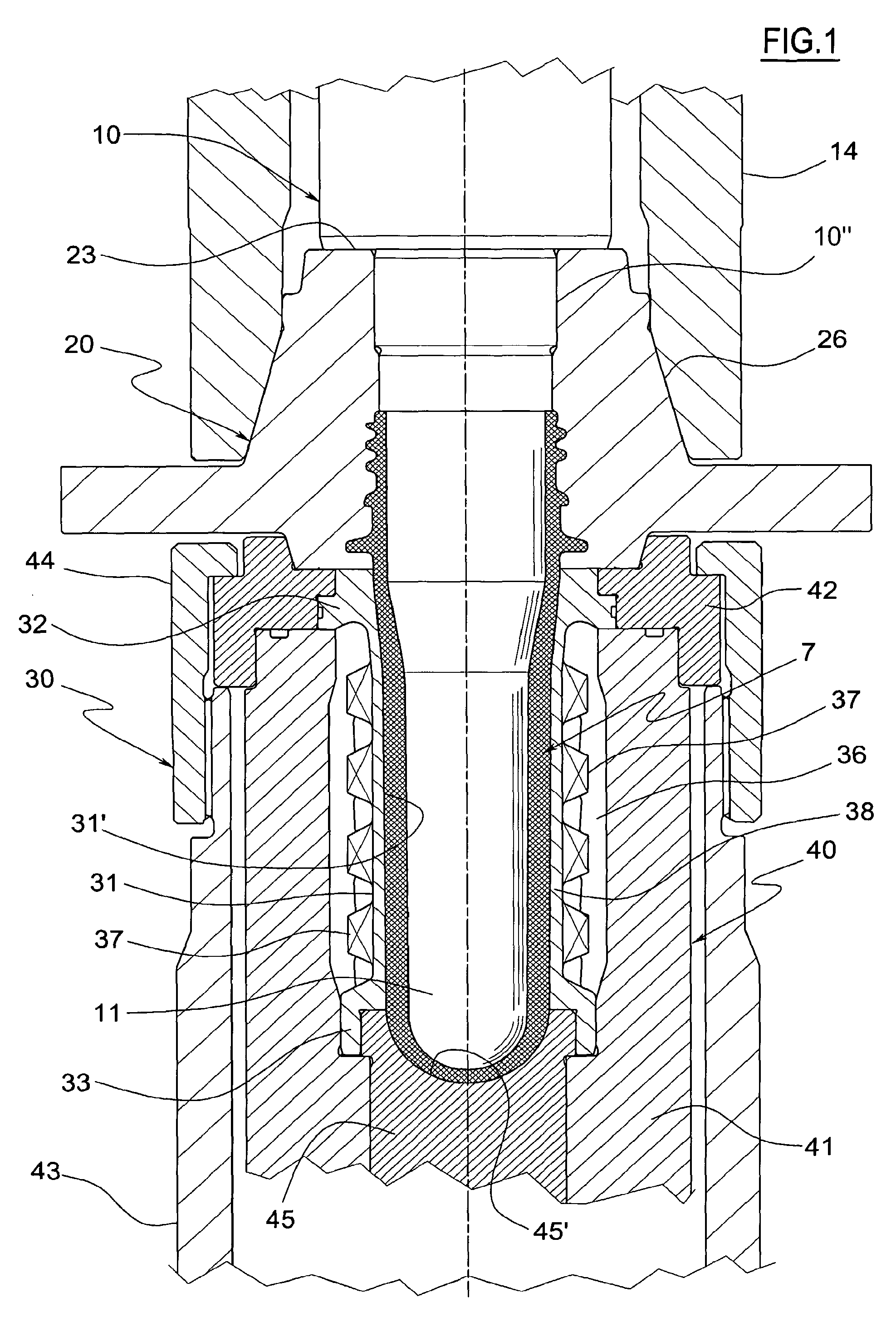
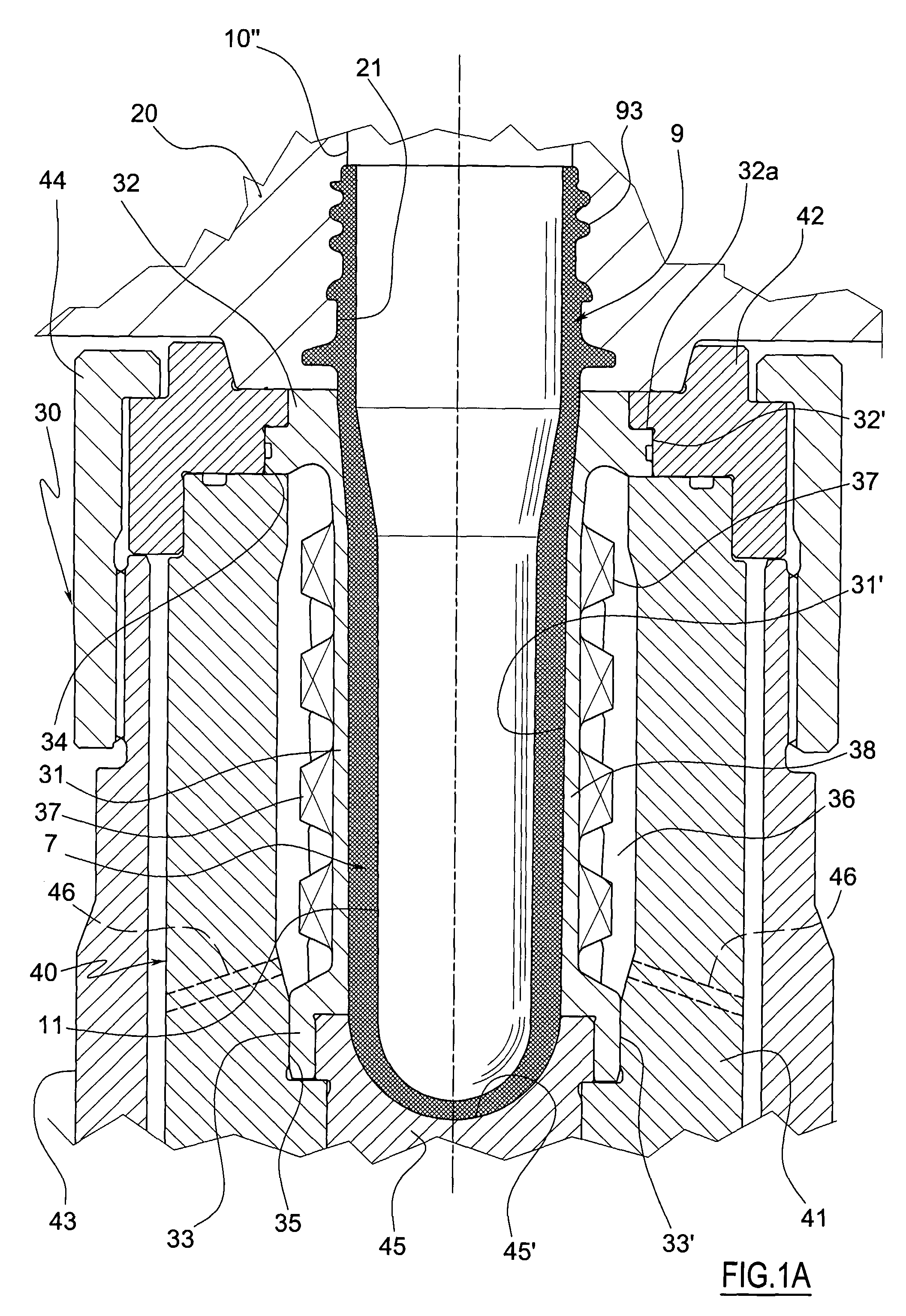
[0040] illustrated in FIG. 1, the lower matrix part 30 comprises a portion 38 having tubular form, in particular substantially cylindrical, which defines said deformable wall 31, whose inner surface 31′ confers the shape, at least in part (and in particular, as illustrated, almost completely) of the outer surface of the side wall 92a of the hollow body 92, which wall 31 has a relatively thin thickness which permits it to be elastically deformed under the pressure of the polymeric material.

[0041]The deformable wall 31 is housed, in particular it is enclosed, within a coaxial cavity 36 made in the support body 40, whose inner surface is placed a distance from the outer surface of the wall 31, such that this may be radially deformed without being hindered by the body 40 itself.

[0042]The deformable wall 31 comprises an enlarged section which defines a circular band 32 near the upper end and a second enlarged section, near the lower end, which defines a second circular band 33. Said circ...

second embodiment

[0074]Therefore, also in this second embodiment, as in the first, the deformable wall 31 comprises a deformable tubular portion 38 which has, along the generic axial section, from one side and the other with respect to the axis, two end portions defined by the circular bands 32 and 33, which form abutments which hinder the radial displacement, and a central portion, laminar and having a relatively thin thickness in relation with the axial length, in a single body with the two end portions, free to elastically bend in radial direction, forming an arch in the axial plane. Moreover it also comprises a deformable bottom portion 39 which has, along generic axial section, two end portions, both defined by the circular band 33, and a central portion, having a relatively thin thickness in relation with the length, free to elastically bend in the axial direction.

[0075]The cavity 36 is connected, through a lower mouth 49 made in the central body 45b and other not-illustrated conduits, with me...

third embodiment

[0082]The cavity 36 is connected, through a lower mouth 52 made in the central body 45b and other not-illustrated conduits, with means adapted to circulate refrigerant fluids in the cavity 36 itself capable of removing heat from the preform in a step of thermal conditioning (cooling) of the same. In the lower part of the cavity 36, below the abutment ribs 51, there are several fins 53 projecting upward from the central body 45b, adapted to better direct the flux of the refrigerant fluid, and which do not hinder the deformation of the wall 31 with which they do not come into contact. Also in this third embodiment, the error of the metering is apportioned also to the bottom portion 92b, in addition to the side portion 92a of the hollow body 92.

[0083]There may moreover be foreseen several conduits 54, made in the support body 40, in particular in the central body 45b and in the fins 53, which cross the ribs 51 and the lower band 33, which lead in correspondence with the surfaces of mut...


PUM

PropertyMeasurementUnit
pressureaaaaaaaaaa
thicknessaaaaaaaaaa
lengthaaaaaaaaaa

Abstract

The preform is formed by an upper neck which maintains unchanged its form in the final object and a hollow body, joined to the neck. The method foresees the insertion, within a matrix cavity, of a metered body of polymeric material whose mass is metered according to a reference value, and the subsequent pressure insertion of a punch within the matrix cavity until it closes the mold's molding chamber, the punch conferring the shape to the inner surface of the preform and the matrix having an inner surface which confers the shape to the outer surface of the preform. According to the invention, in the molding of the preform, the error of the mass of the metered body with respect to the reference value is distributed in the hollow body, which undergoes a subsequent hot deformation until it achieves the final shape. In the mold, the matrix comprises at least one deformable wall (31) whose inner surface defines at least part of the inner surface of the matrix part intended to give form to the hollow body of the preform, said deformable wall (31) having, at least in part, a relatively thin thickness which permits it to be elastically deformed under the pressure of the polymeric material in the final preform molding step, thereby varying the thickness of the hollow body.

Description

TECHNICAL FIELD[0001]The present invention relates to the compression molding of (semi-finished) preforms intended for the subsequent realisation (typically through stretch blow molding) of concave objects, such as bottles, in polymeric material.[0002]The preform comprises an upper neck which maintains unchanged the shape of the final object and a hollow body, placed below the neck, which is instead dilated until it assumes a much greater capacity and a correspondingly reduced thickness.PRIOR ART[0003]According to present technique, to form the preform it is first foreseen the insertion, within a rigid metal matrix (in steel) of a metered body of polymeric material whose mass is metered according to a pre-established value such to completely and exactly fill the molding chamber of the mold, and, subsequently, the pressure insertion of a punch within the same matrix cavity until it closes the mold's molding chamber, i.e. the chamber which, when the mold is in closed position, remains...

Claims


Application Information

Patent Timeline
Patent Type & Authority Patents(United States)
IPC IPC(8): B29C49/02B29C43/02B29C43/54
CPCB29C33/0011B29C43/36B29C43/361B29C43/52B29C43/3642B29B2911/14713B29B2911/1498B29C33/308B29K2105/253B29C2043/3652B29C2043/5841B29C2043/5883B29L2031/565B29C2949/0829B29C2949/0872
Inventor BALBONI, ALESSANDROPARRINELLO, FIORENZOZUFFA, ZENO
Owner SACMI COOP MECCANICI IMOLA SOC COOP A R L
Why Eureka
Try Eureka