Power conversion device frame packaging apparatus and methods

a power conversion device and packaging technology, applied in the direction of electrical apparatus construction details, electrical apparatus casings/cabinets/drawers, coupling device connections, etc., can solve the problems of increasing the cost and complexity of a product line, multiple versions of printed circuit boards also increasing distribution costs, etc., to increase the flexibility of products, quick packaging and shipping, and fast response

Inactive Publication Date: 2011-05-10
PEI GENESIS
View PDF56 Cites 18 Cited by
  • Summary
  • Abstract
  • Description
  • Claims
  • Application Information

AI Technical Summary

Benefits of technology

[0022]From a supply chain management point of view, the present invention increases the flexibility of the product. Most notably, a single PCB can be packaged in many different ways. The PCB and packages can be manufactured in large volumes at a remote location and held in stock at a distribution location close to the market. When a customer places an order the power supply can be quickly packaged and shipped to the customer. This approach will result in fast response to customers with minimum inventory investments.

Problems solved by technology

While this will tend to optimize the design of each particular power supply and package combination, it greatly adds to the cost and complexity of a product line.
In addition to the increased cost to design and produce multiple circuit boards, this approach adds cost and complexity since each printed circuit board must be designed, tested, and approved by the appropriate safety agencies.
Finally, multiple versions of the printed circuit board also increases distribution costs since many similar parts must be held in inventory to fully stock the distribution channel.

Method used


Image

  • Power conversion device frame packaging apparatus and methods
  • Power conversion device frame packaging apparatus and methods
  • Power conversion device frame packaging apparatus and methods

Examples


Embodiment Construction

[0056]Although this invention is susceptible to embodiments of many different forms, a preferred embodiment will be described and illustrated in detail herein. The present disclosure exemplifies the principles of the invention and is not to be considered a limit to the broader aspects of the invention to the particular embodiment as described.

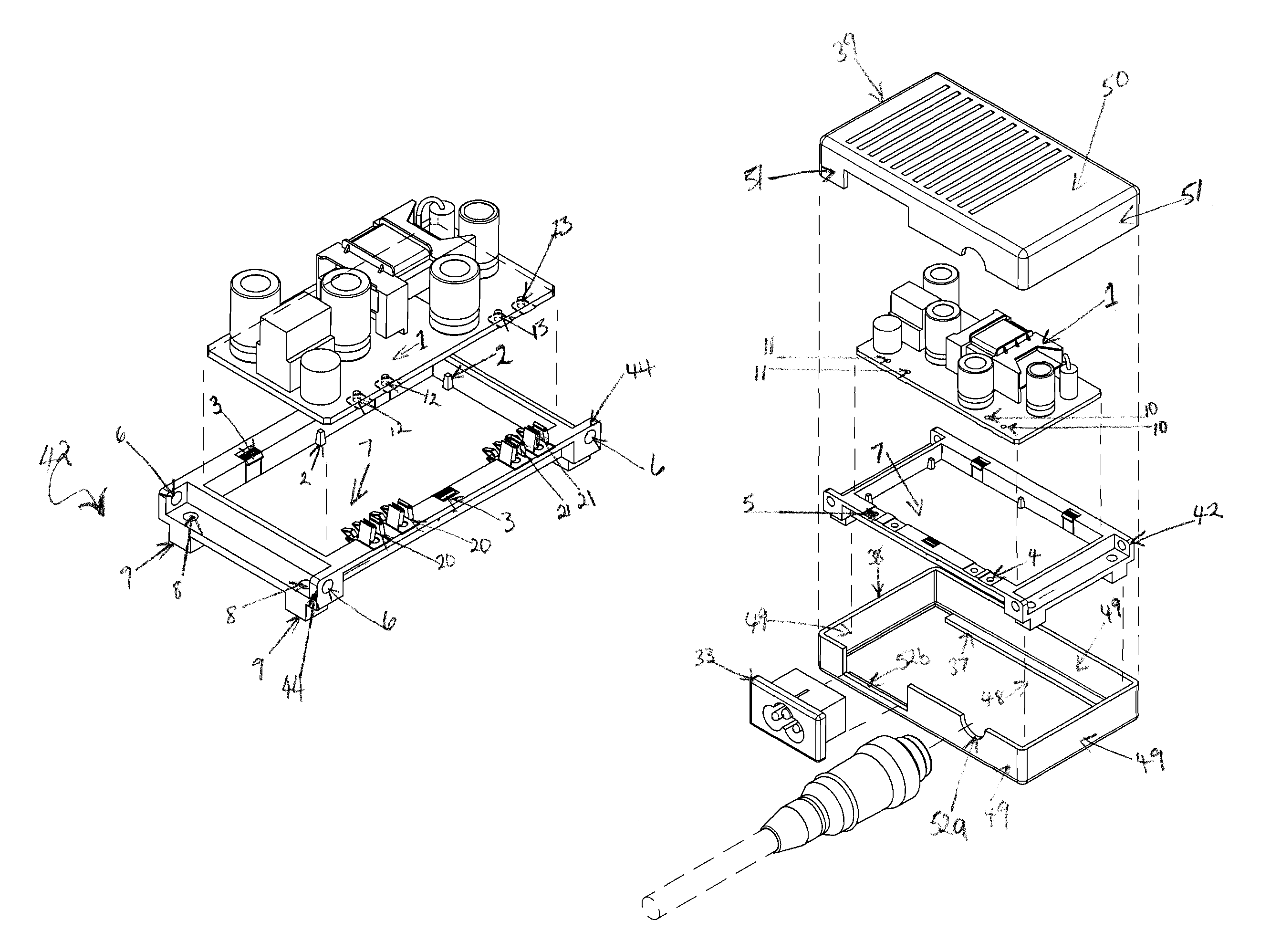
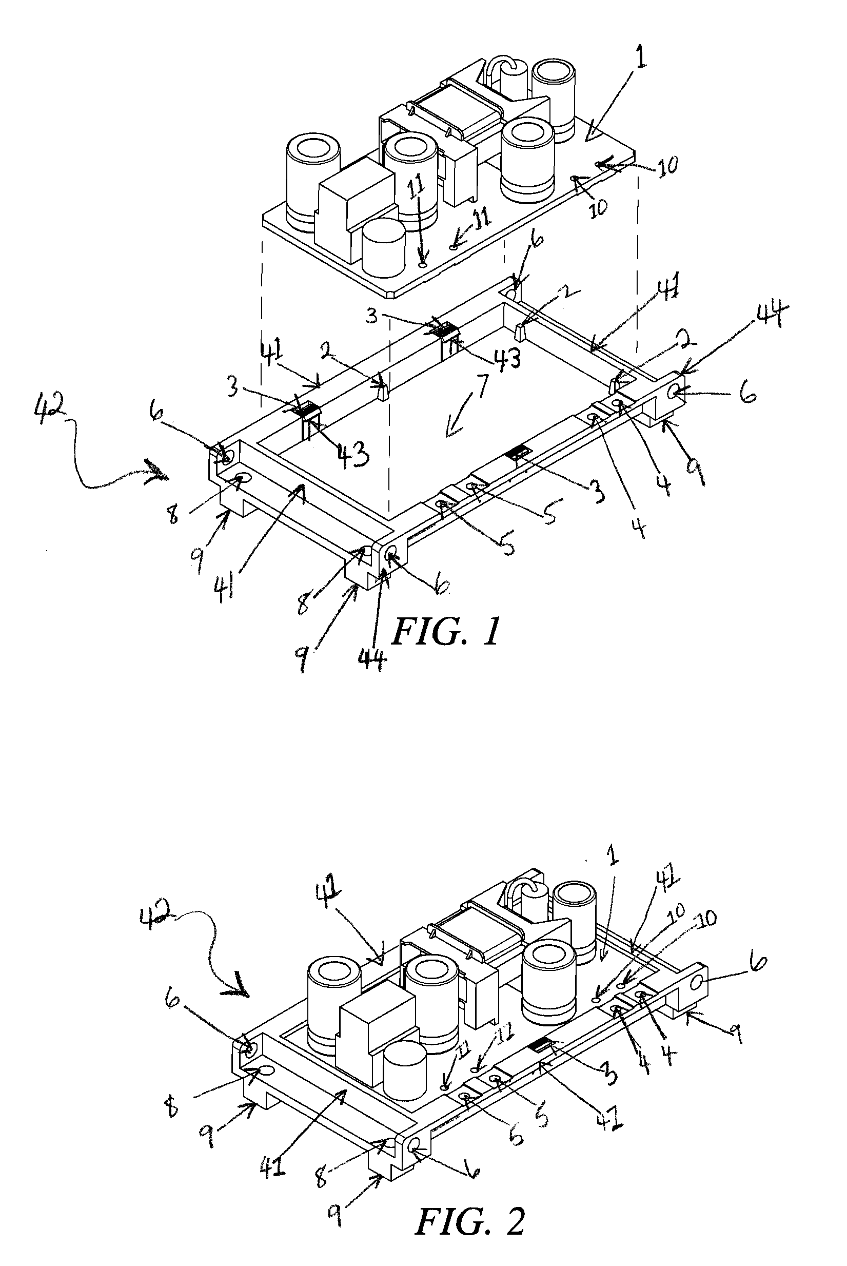
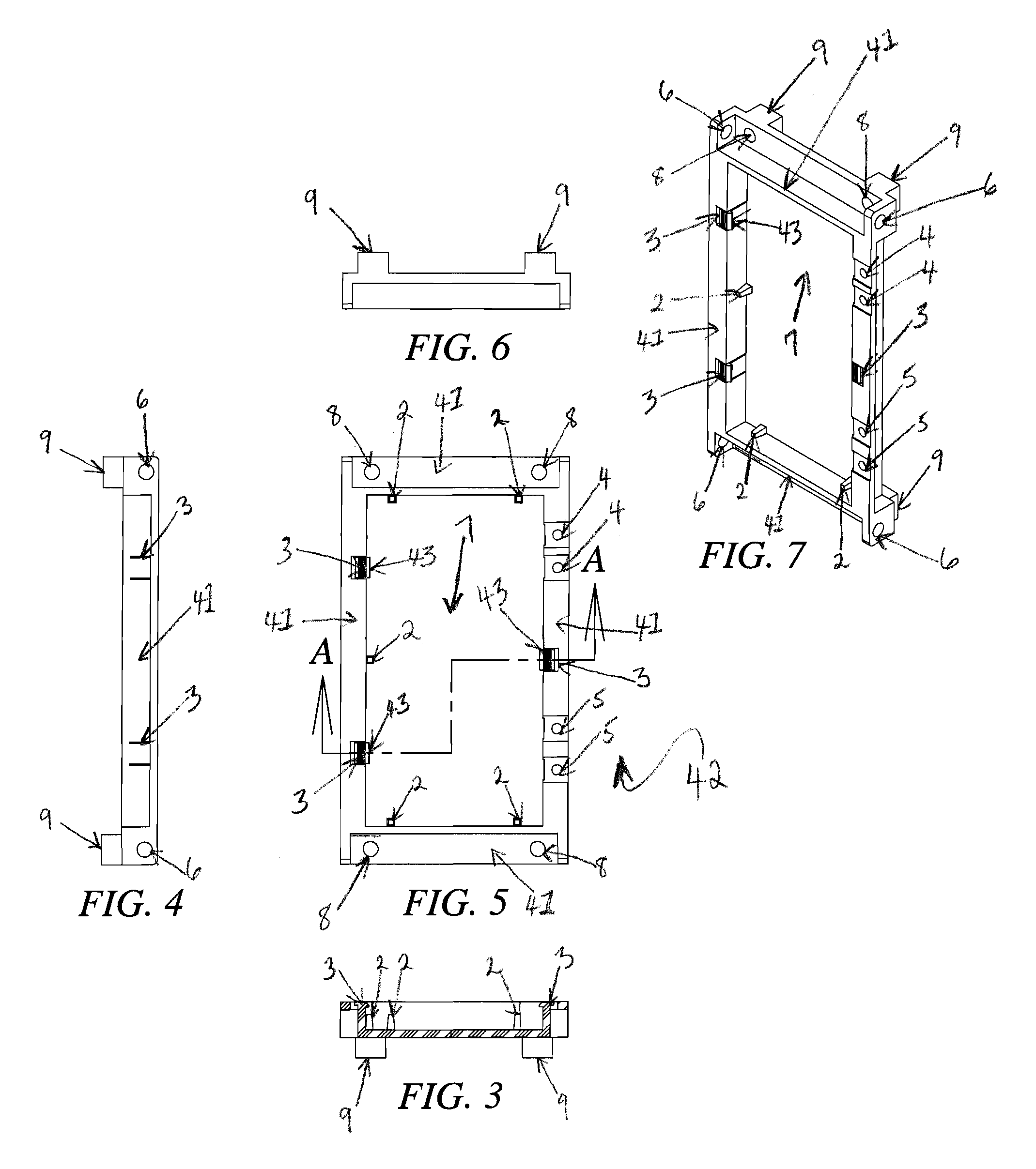
[0057]The present invention relates, generally, to electrical power conversion devices and to the universal packaging of those devices for a wide range of applications yielding cost efficient inventory management of product lines consisting of a group of power conversion devices each with minor variations. More specifically, the present invention relates to a universal mounting frame for receiving a printed circuit board in a switch mode power supply. The universal frame is adapted for receiving an open frame or printed circuit board and securing the open frame within a plurality of known packaging configurations. To this end, only a single siz...


PUM


Abstract

The present invention relates, generally, to electrical power conversion devices and to the universal packaging of those devices for a wide range of applications yielding cost efficient inventory management of product lines consisting of a group of power conversion devices each with minor variations. More specifically, the present invention relates to a universal mounting frame for receiving a printed circuit board in a switch mode power supply. The universal frame is adapted for receiving an open frame or printed circuit board and securing the open frame within a plurality of known packaging configurations. To this end, only a single size printed circuit board is necessary for any type of switch mode power supply configurations, thereby, reducing costs associated with manufacture and testing.

Description

CROSS-REFERENCE TO RELATED PATENT APPLICATIONS[0001]This patent application is a continuation-in-part of U.S. patent application Ser. No. 11 / 820,476, filed Jun. 18, 2007, which is a continuation of U.S. patent application Ser. No. 11 / 075,539, filed 9 Mar. 2005, (now abandoned) which claims the benefit, under the applicable provisions of 35 U.S.C. 119 and 120, of the priority of U.S. provisional patent application Ser. No. 60 / 551,915, entitled “Frame Packaging System for Power Conversion Devices, filed 10 Mar. 2004, the disclosure of which is hereby incorporated by reference in its entirety.FIELD OF THE INVENTION[0002]The present invention relates, generally, to electrical power conversion devices and more specifically to the packaging of those devices for a wide range of applications as well as for cost efficient inventory management of product lines consisting of a group of power conversion devices each with minor variations.BACKGROUND[0003]Switch mode power supplies are widely use...

Claims


Application Information

Patent Timeline
Patent Type & Authority Patents(United States)
IPC IPC(8): H05K7/14
CPCH02M7/003H05K1/0263H05K2201/2018H05K2201/10424H05K2201/1059H05K2201/09954
Inventor WILLING, STEVEN LEECARLSON, KENTCAMPBELL, ROBERT E.AVENDANO, ALBERTO
Owner PEI GENESIS
Why Eureka
Try Eureka