Waterproof structure

a technology of water-proof structures and diaphragms, which is applied in the direction of telephone set construction, substation equipment, interconnection arrangements, etc., can solve the problems of end portion of waterproof diaphragms, affecting the waterproofing ability, and may come out du

Inactive Publication Date: 2011-05-10
LENOVO INNOVATIONS LTD HONG KONG
View PDF25 Cites 112 Cited by
  • Summary
  • Abstract
  • Description
  • Claims
  • Application Information

AI Technical Summary

Benefits of technology

[0008]Accordingly, to overcome the problem, it is an object of the present invention to provide a waterproof structure which makes it harder for water to penetrate inside casings. Specifically, it is an object of the present invention to provide a waterproof structure which can easily fix separate casings with fewer screws, and prevent a waterproof member from coming out due to vibration or the like, making it harder for water to penetrate inside the casings.
[0012]a waterproof member formed of an elastic material to prevent water from penetrating between the first casing and the second casing,
[0014]the waterproof member having a protruding seal part which, when fitted into the recess, prevents penetration of water and has a projection engageable with the dent when being inserted in the dent.

Problems solved by technology

The end portion of the waterproof diaphragm, if merely press fitted in the recessed groove provided at the case, may come out due to vibration or the like.
This impairs the waterproofing capability.

Method used


Image

  • Waterproof structure
  • Waterproof structure
  • Waterproof structure

Examples


first embodiment

[0026]An embodiment of the present invention will now be described with reference to the accompanying drawings.

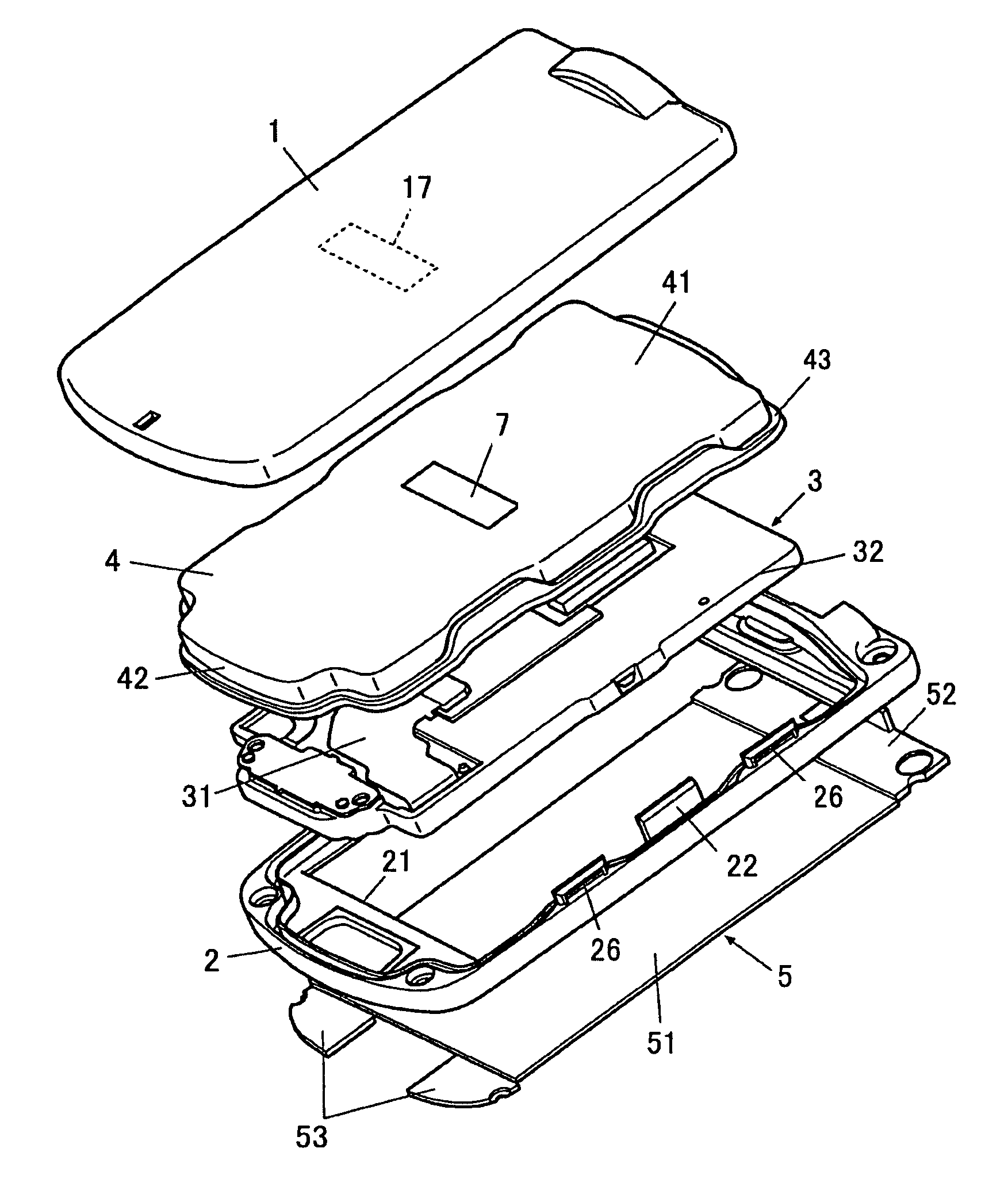
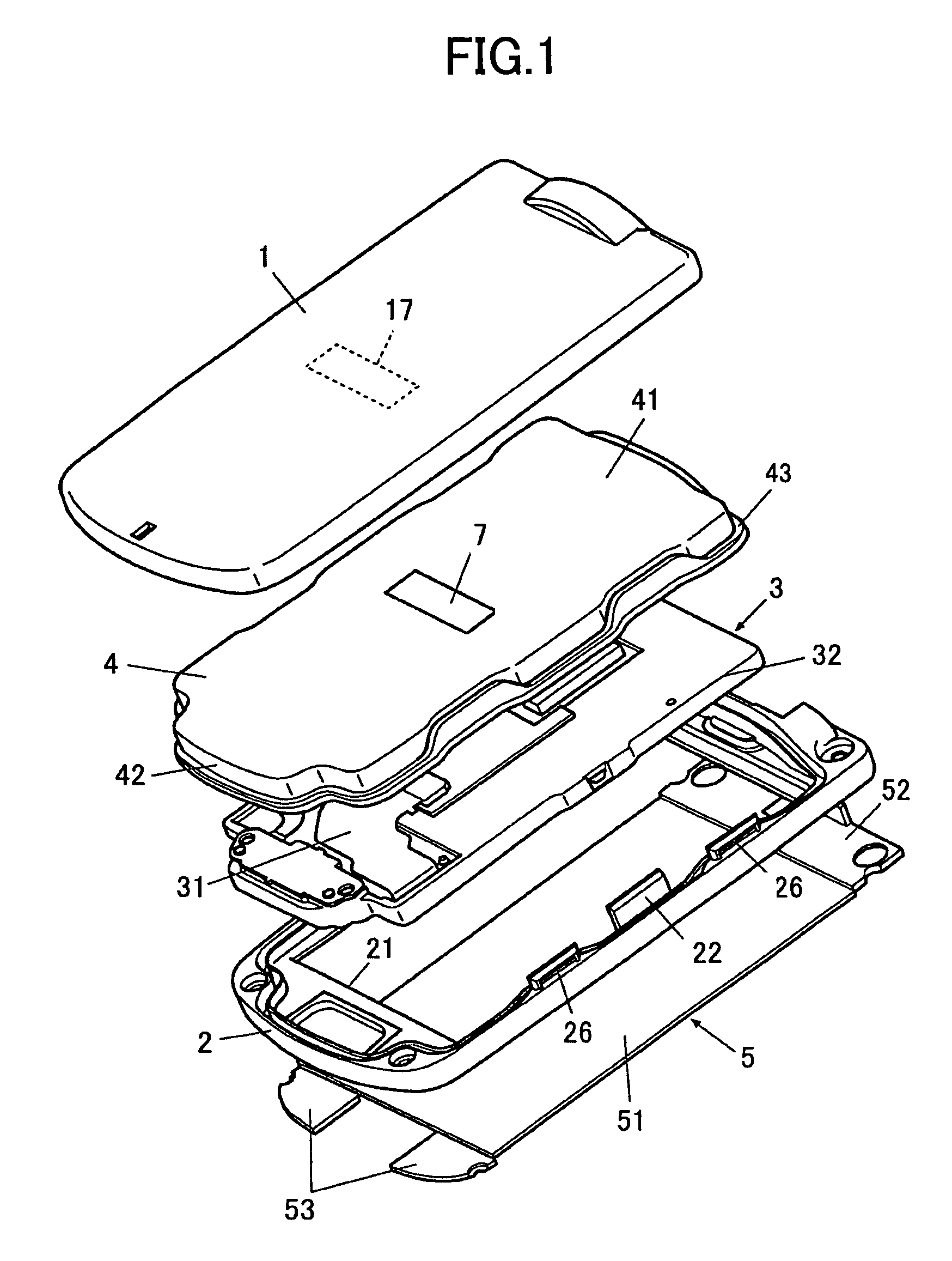
[0027]As shown in FIG. 1, a waterproof structure according to the embodiment has a first casing 1, a second casing 2, an interior trim 3, a waterproof member 4 and an exterior trim 5.

[0028]In the embodiment, the waterproof structure is adapted to the first casing 1 and the second casing 2 which constitute the display side body of a fold type cellular phone. The interior trim 3 that is to be accommodated between the first casing 1 and the second casing 2 comprises a liquid crystal display (LCD) panel 31 and a shield case 32 thereof. The waterproof member 4 is a film-like rubber packing. As the material for the waterproof member 4, polybutadiene, polyacrylonitrile or the like can be used. The exterior trim 5 has a hinge piece 52 at one end side of a transparent panel 51 and a pair of screw screens 53 at the other side of the transparent panel 51.

[0029]The display side body is...

second embodiment

[0053]FIG. 5 shows a waterproof structure according to the second embodiment of the present invention. The waterproof structure according to the second embodiment differs from that of the first embodiment in that the waterproof member 4 has a metal plate 110.

[0054]The metal plate 110 has an approximately rectangular shape as seen from the top, as shown in FIG. 5. It is to be noted that the upper two corners in FIG. 5 and a lower center portion in FIG. 5 of the rectangular shape are cut away. Accordingly, the metal plate 110 has cutaway portions 110a, 110a and a cutaway portion 110b at the above-specified locations.

[0055]To emphasize the presence of the cutaway portions (110a, 110b), FIG. 5 shows, by broken lines, the contour shapes in an assumed case where the cutaway portions are not present.

[0056]A window 511 having an approximately rectangular shape is formed in the metal plate 110 as indicated by the lower left portion in FIG. 5. The window 511 is formed in a forming region for ...

third embodiment

[0084]FIG. 7 shows a section of the waterproof structure according to the third embodiment of the present invention. The waterproof structure according to the third embodiment differs from that of the first embodiment in that the waterproof member 4 has the metal plate 110. The metal plate 110 is provided at a position inward of the casings and extending from the circumferential wall part 42 approximately horizontally. The metal plate 110 is formed of stainless steel. The metal plate 110 is formed to have a thickness of 1.0 to 5.0 mm.

[0085]The metal plate 110 has a first hook 120 which is bent toward the second casing 2 at a position 115 inward of an end portion 114 of the metal plate 110 by a predetermined distance, and is bent toward the first casing 1 at a position 116 slightly outward of the inward-bent position, the first hook 120 having an end portion 121 protruding from the circumferential wall part 42.

[0086]The second casing 2 has the recess 23 formed between a first project...


PUM


Abstract

A waterproof structure for a casing has a first casing, a second casing to be put together with the first casing, and a waterproof member formed of an elastic material to prevent water from penetrating between the first casing and the second casing. The second casing has a recess. The waterproof member has a peripheral part which, when fitted into the recess, prevents penetration of water. The peripheral part is provided at the periphery of the waterproof member, which is laid out all around space between the first casing and the second casing. A projection engages with a dent. A restriction part of the first casing, provided at a position facing the peripheral part and protruding toward the second casing, prevents the peripheral part from coming out.

Description

BACKGROUND OF THE INVENTION[0001]1. Field of the Invention[0002]The present invention relates to a waterproof structure of a casing of a portable electronic device or the like.[0003]2. Description of the Related Art[0004]There are waterproof structures for a portable transmitter each of which holds a peripheral end portion of a waterproof cover between two separate cases, as described in Unexamined Japanese Patent Application KOKAI Publication Nos. H11-288635 and 2004-312621.[0005]There is also a waterproof structure for a weighing machine in which an end portion of a waterproof diaphragm is press fitted in a recessed groove provided at a case, as described in Unexamined Japanese Patent Application KOKAI Publication No. 2003-322556.[0006]If the end portion of the waterproof cover is held by the separate two cases from above and bottom, however, elastic force acts in the vertical (up and down) direction. It is therefore necessary to provide a lot of screws or a lot of hook parts to f...

Claims


Application Information

Patent Timeline
Patent Type & Authority Patents(United States)
IPC IPC(8): H04M1/00
CPCH04B1/3888H04M1/18H04M1/0249H04B1/38
Inventor KAWASAKI, YASUHIKOBABA, TAKERUMURAKAMI, TOSHIYUKIKATO, SHIGERUYAMAGUCHI, TSUTOMU
Owner LENOVO INNOVATIONS LTD HONG KONG
Why Eureka
Try Eureka