Self-exciting, self-sensing piezoelectric cantilever sensor

a piezoelectric, self-sensing technology, applied in the field of sensors, can solve the problems of liquid dampening, affecting sensitivity, and limiting the bending of the cantilever arm,

Inactive Publication Date: 2011-05-17
DREXEL UNIV
View PDF43 Cites 26 Cited by
  • Summary
  • Abstract
  • Description
  • Claims
  • Application Information

AI Technical Summary

Problems solved by technology

Macro-cantilever sensors typically are not utilized in the static mode because bending of the cantilever arm is often limited.
Liquid dampening tends to adversely affect sensitivity.
One disadvantage of typical silicon-based micro-cantilevers is the complex external optical components required for detection.
Further, optical detection means disadvantageously limit application of the micro-cantilever sensor to optically clear samples.
Another disadvantage is the weight and complexity added to the sensor due to the external actuator.
Yet another disadvantage is that the external actuator can be located only at the base of the micro-cantilever, which limits its effectiveness in driving the cantilever's vibration.
A further disadvantage of silicon-based micro-cantilever sensors is that they are mechanically fragile.
Thus, silicon-based micro-cantilever sensors can not be used in high liquid flow rate environments.
Further, typical silicon-based micro-cantilever sensors lose detection sensitivity in liquid media due to viscous damping.
Quartz is a weak piezoelectric, and thus, much like silicon-based cantilever sensors, quartz-based piezoelectric cantilever sensors lose detection sensitivity in liquid media due to viscous damping.
Further, the detection sensitivity of quartz-based sensors is limited by the planar geometry of the sensor.
However, reducing the dimensions of the cantilever sensor, particularly the width, thusly, makes the cantilever sensor less usable in a liquid medium due to viscous damping.

Method used


Image

  • Self-exciting, self-sensing piezoelectric cantilever sensor
  • Self-exciting, self-sensing piezoelectric cantilever sensor
  • Self-exciting, self-sensing piezoelectric cantilever sensor

Examples


Embodiment Construction

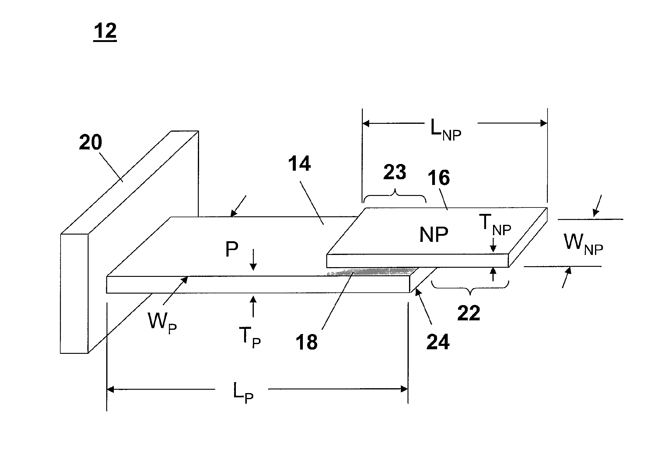
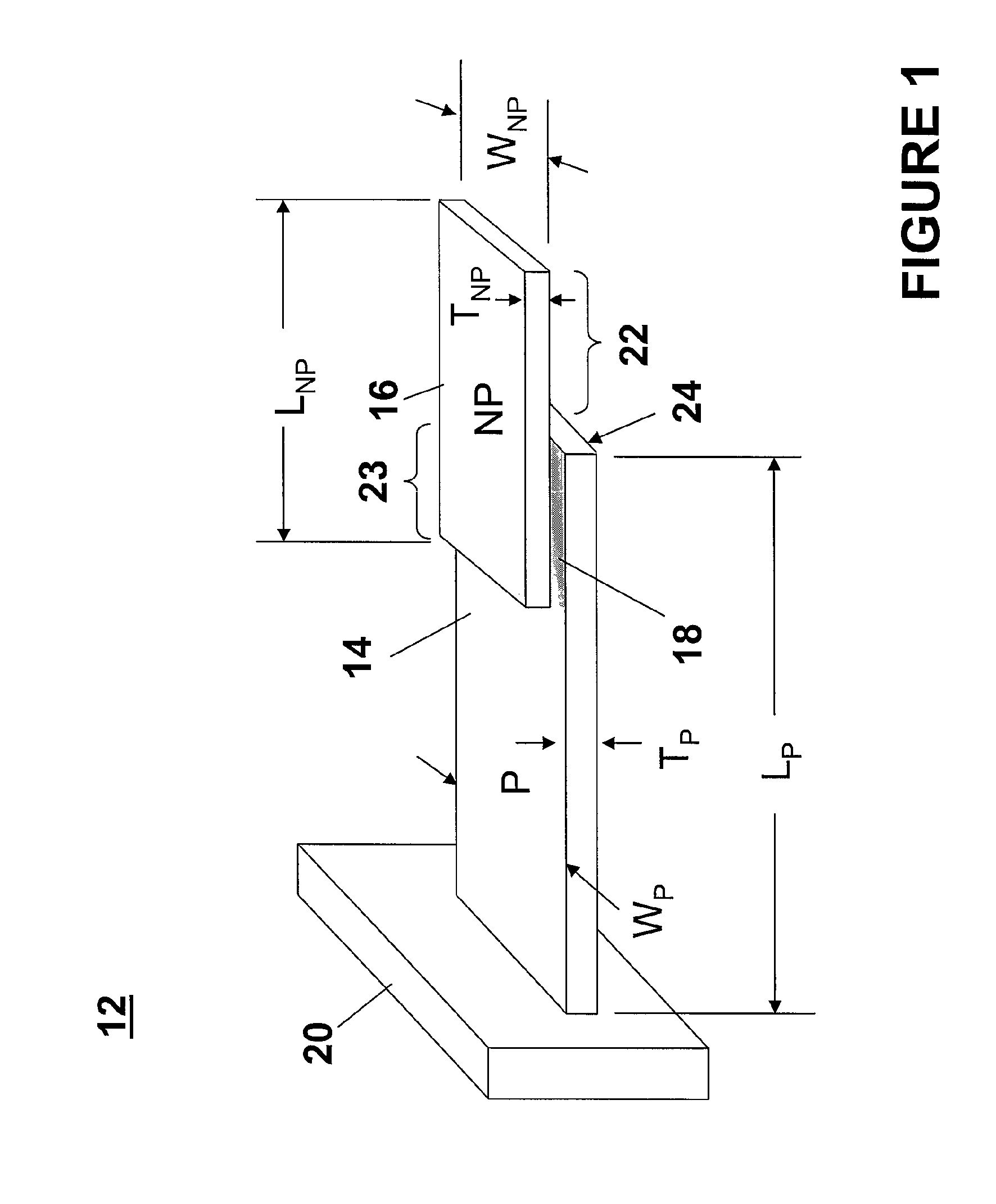
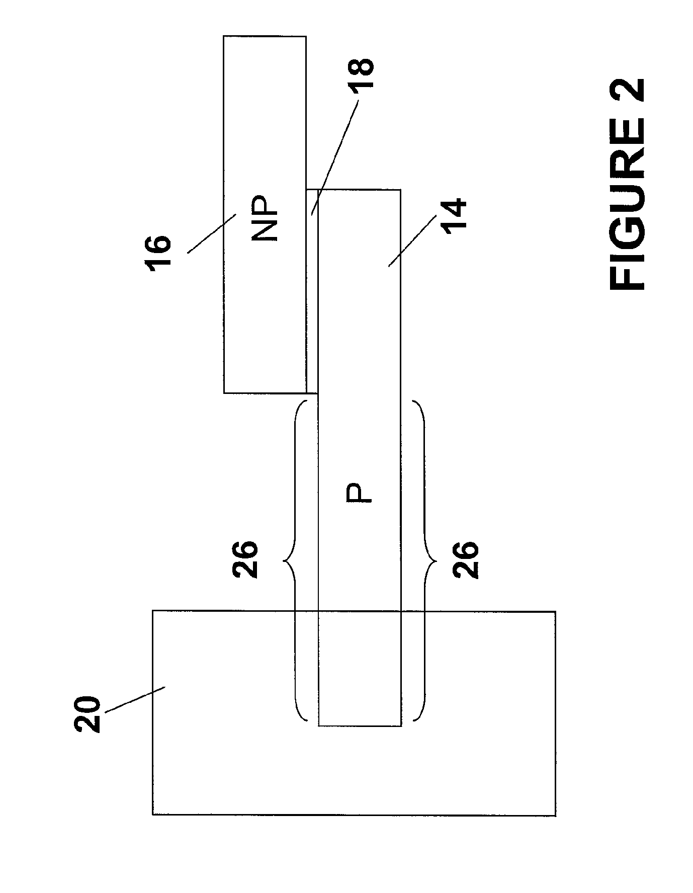
[0027]A self-exciting, self-sensing piezoelectric cantilever sensor as described herein provides the ability to detect and measure extremely small amounts of an analyte. The self-exciting, self-sensing piezoelectric cantilever sensor can be utilized to detect and measure an analyte immersed in a liquid and an analyte contained in a gas or vacuum. In various example configurations, the self-exciting, self-sensing piezoelectric cantilever sensor comprises at least one piezoelectric layer and at least one non-piezoelectric layer, wherein the piezoelectric layer is coupled to the non-piezoelectric layer such that the piezoelectric layer and the non-piezoelectric layer are not coextensive. The piezoelectric layer, the non-piezoelectric layer, or both can be coupled to at least one base. The piezoelectric layer and the non-piezoelectric layer can be of varying widths, lengths, and thicknesses.

[0028]The self-exciting, self-sensing piezoelectric cantilever sensor is utilizable to determine ...


PUM


Abstract

A piezoelectric cantilever sensor includes a piezoelectric layer and a non-piezoelectric layer, a portion of which is attached to the piezoelectric layer. In one embodiment, one end of the non-piezoelectric layer extends beyond the end of piezoelectric layer to provide an overhang. The overhang piezoelectric cantilever sensor enables increased sensitivity allowing application of the device in more viscous environments, such as liquid media, as well as application in liquid media at higher flow rates than conventional piezoelectric cantilevers. In another embodiment, the sensor includes first and second bases and at least one of the piezoelectric layer and the non-piezoelectric layer is affixed to each of the first and second bases to form the piezoelectric cantilever sensor. In this embodiment, the sensor is robust and exhibits excellent sensing characteristics in both gaseous and liquid media, even when subjected to relatively high flow rates.

Description

CROSS REFERENCE TO RELATED APPLICATIONS[0001]The present application claims priority to U.S. Provisional Patent application No. 60 / 761,172, entitled “PIEZOELECTRIC CANTILEVER SENSORS,” filed Jan. 23, 2006, and U.S. Provisional Patent Application No. 60 / 807,020, entitled “PIEZOELECTRIC CANTILEVER SENSORS,” filed Jul. 11, 2006, both of which are hereby incorporated by reference in their entirety.TECHNICAL FIELD[0002]The technical field generally relates to sensors, and more specifically relates to piezoelectric cantilever sensors and to detecting and measuring analytes utilizing a piezoelectric cantilever sensor.BACKGROUND[0003]Cantilever sensors can be broadly divided into two categories, depending upon dimensions of the sensor: micro-cantilevers and macro-cantilevers. Micro-cantilever sensors can be utilized in both static (bending) mode and dynamic (resonance) mode. In static mode, the deformation of the cantilever arm is measured to determine if an analyte (substance under analysi...

Claims


Application Information

Patent Timeline
Patent Type & Authority Patents(United States)
IPC IPC(8): G01H1/00
CPCG01H11/08G01H13/00G01N29/022G01N29/036H01L41/1132G01N33/54373G01N2291/0256G01N2291/0426G01N2291/0427H10N30/302
Inventor MUTHARASAN, RAJAKKANNUMARALDO, DAVIDCAMPBELL, GOSSETT AUGUSTUSRIJAL, KISHAN
Owner DREXEL UNIV
Why Eureka
Try Eureka