Method and system for multi-path ultrasonic flow rate measurement

a multi-path, ultrasonic technology, applied in the direction of instruments, liquid/fluent solid measurement, pulse characteristics measurement, etc., can solve the problems of increasing the cost of the flow meter, increasing the difficulty of installation of a large number of transducers, and only providing moderate to high accuracy

Active Publication Date: 2011-05-17
GE INFRASTRUCTURE SENSING
View PDF39 Cites 22 Cited by
  • Summary
  • Abstract
  • Description
  • Claims
  • Application Information

AI Technical Summary

Problems solved by technology

While these prior art solutions minimize the need to determine some installation-specific pieces of information required to determine the flow profile, the solutions only provide moderate to high accuracy for a flow profile that requires a high order polynomial required to describe it (i.e., the higher the complexity of the flow profile, the higher the order of the polynomial) unless there are sufficient ultrasonic paths and transducers provided in the ultrasonic flow meter to improve the accuracy.
For example, if a 15th order polynomial is required to describe the flow profile, a total of eight ((15+1) / 2) ultrasonic paths and transducer pairs can be required for improved accuracy, which would also increase the cost of the flow meter, increase the difficulty of installation of large number of transducers given the space constraints on a pipe, and increase the disturbances to the flow causes by the large number of transducer ports.
Furthermore, since several ultrasonic flow meter applications require highly accurate flow rate (Vm) measurements (e.g., custody-transfer applications for liquid hydrocarbons often require an accuracy of 0.15%) that cannot always be achieved by simply increasing the number of ultrasonic paths and transducers in these prior art solutions, complicated calibration schemes using calibration factors that are based on several of the physical properties of the fluid and / or the pipe (e.g., the Reynolds number) are required anyway to achieve the required accuracy, which increases the costs and complexity of the flow meters.

Method used


Image

  • Method and system for multi-path ultrasonic flow rate measurement
  • Method and system for multi-path ultrasonic flow rate measurement
  • Method and system for multi-path ultrasonic flow rate measurement

Examples


Embodiment Construction

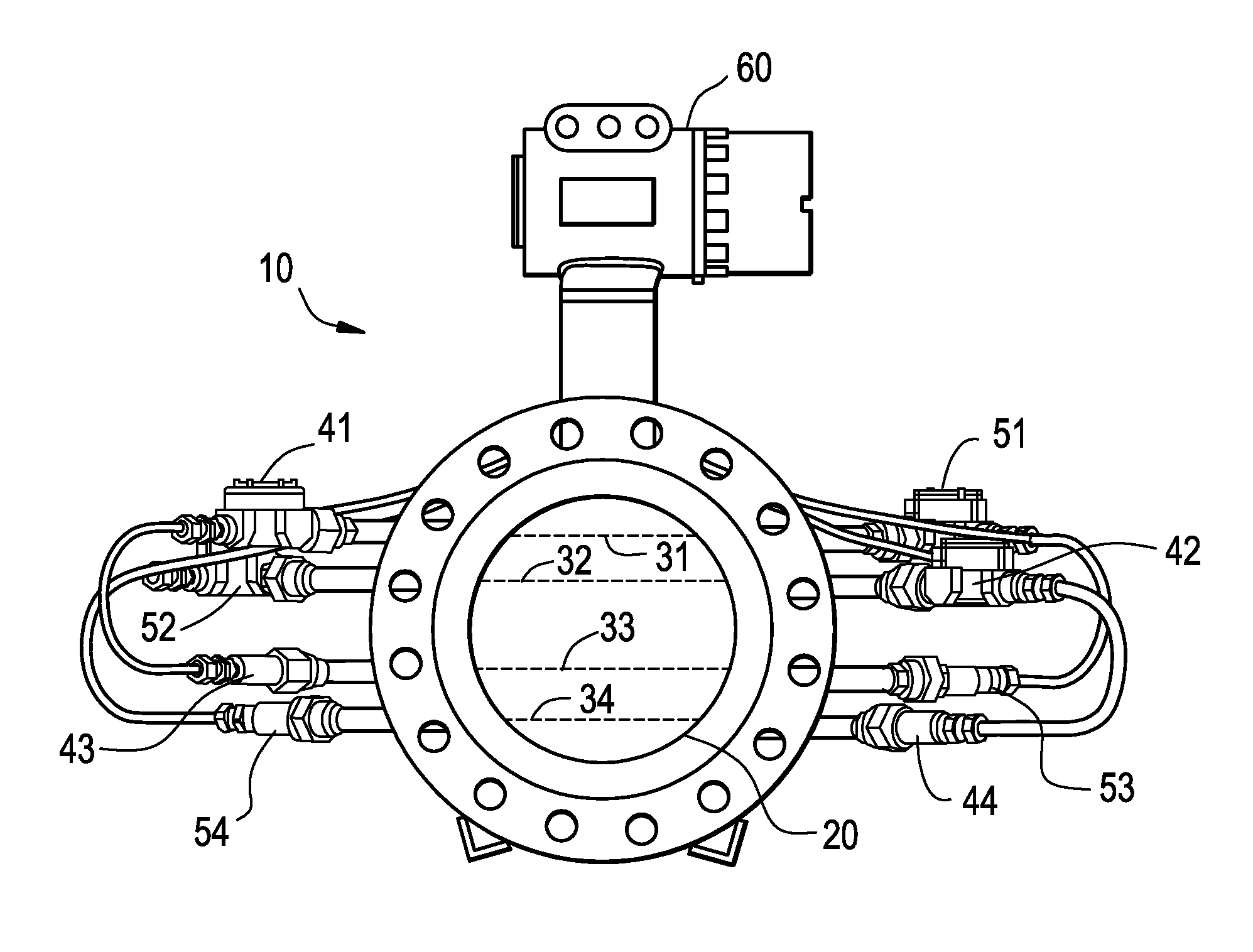
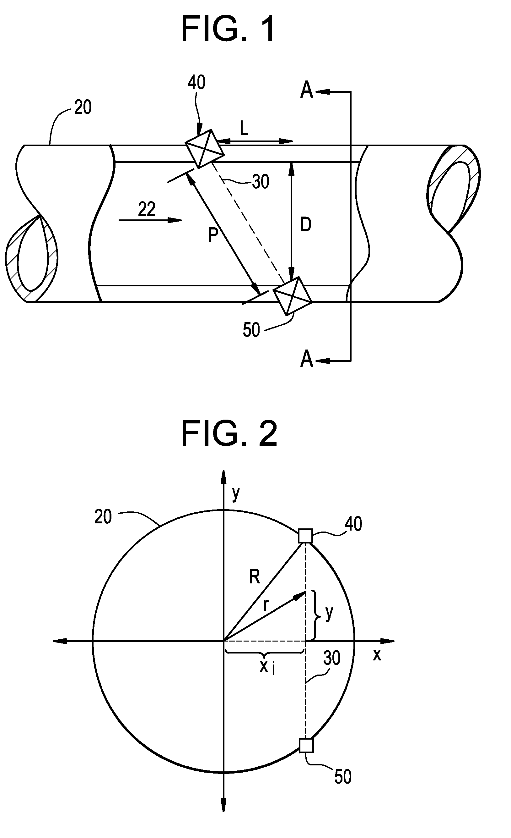
[0018]FIG. 1 illustrates an ultrasonic flow meter 1 employing transit time flow metering to determine the flow rate of a fluid. Although FIG. 1 shows a single pair of transducers 40, 50 attached to a conduit 20 forming a single ultrasonic path 30, it will be understood by a person of ordinary skill in the art that two or more pairs of transducers 40, 50, each forming separate ultrasonic paths, can be used to form a multi-path ultrasonic flow meter. Based on the fluid flow direction 22, one transducer 40 can be installed upstream of the downstream transducer 50 on the conduit 20, which can be a section of the pipe or a separate spool piece hot-tapped to the pipeline. The ultrasonic path 30 can be on the center (i.e., diameter (D)) of the conduit 20 or on chordal paths (i.e., path not on the center of the conduit 20). Each transducer 40, 50, when energized, transmits an ultrasonic signal along the ultrasonic path 30 through the flowing fluid that is received by and detected by the oth...


PUM


Abstract

In one embodiment, a multi-path ultrasonic flow meter for determining the flow rate of a fluid in a conduit is disclosed comprising at least two transducer pairs attached to the conduit at two chord locations, one greater than and one less than a mid-radius chord, wherein the composite ratio the two path velocities to the flow rate is substantially constant over the range of Reynolds numbers. In another embodiment, a method of determining the flow rate of a fluid in a conduit is disclosed comprising the steps of determining a composite velocity by determining a weighted average of a plurality of path velocities, determining a chord velocity ratio based on the path velocities, determining a profile correction factor based on the composite velocity and the chord velocity ratio, and determining the flow rate based on the composite velocity and the profile correction factor.

Description

BACKGROUND OF THE INVENTION[0001]This invention relates generally to ultrasonic flow rate measurement, and more particularly to multi-path ultrasonic flow meter.[0002]Ultrasonic flow meters are used to determine the flow rate (i.e., mean pipe flow rate (Vm)) of a variety of fluids (e.g., liquids, gases, etc.) and speed of sound in the fluid flowing in pipes of different sizes and shapes. Knowledge of the flow rate of the fluid can enable other physical properties or qualities of the fluid to be determined. For example, in some custody-transfer applications, the flow rate can be used to determine the volume (Q) of a fluid (e.g., oil or gas) being transferred from a seller to a buyer through a pipe to determine the costs for the transaction, where the volume is equal to the flow rate multiplied by the cross sectional area (A) of the pipe. In other applications, the speed of sound can be used to determine the mean molecular weight of a fluid flowing in a pipe to optimize and control ch...

Claims


Application Information

Patent Timeline
Patent Type & Authority Patents(United States)
IPC IPC(8): G01F1/66G06F19/00
CPCG01F25/0007G01F1/667G01F25/10
Inventor AO, XIAOLEI SHIRLEYCARAVANA, ROBERTFURLONG, EDWARD RANDALLKHRAKOVSKY, OLEG ALEXANDERMCDONALD, BENJAMIN EDWARDMOLLO, NICHOLAS JOSEPHSHEN, LYDIA
Owner GE INFRASTRUCTURE SENSING
Why Eureka
Try Eureka