Flow rate sensor

Active Publication Date: 2011-05-17
VSE VOLUMENTECHNIK GMBH
View PDF20 Cites 4 Cited by
  • Summary
  • Abstract
  • Description
  • Claims
  • Application Information

AI Technical Summary

Benefits of technology

[0021]As the signals of the sensor are markedly stronger and of greater magnitude than in conventional instruments, they may be processed better and with less trouble in downstream devices, such as pre-amplifiers or evaluation devices.
[0037]It is also advantageous that the corresponding sensors for the flow rate sensors according to the invention are very practicable and economical to manufacture. The printed circuit boards are manufactured in panels and their components are automatically fitted.

Problems solved by technology

In connection with flow rate sensors, however, giant magnetoresistance has previously not yet been used.
Such arrangements are however unsuitable for volume sensors because in these there always has to be two mutually meshing gear wheels mounted in a narrow housing with close tolerances.
Given an arrangement of the GMR sensors as proposed, only the tooth tips are scanned, this leading to an inaccurate and asymmetrical electrical signal and hence to corresponding and accurate measurements of the flow quantities and flow rates.
Furthermore, there is no room laterally alongside the gear wheels, and / or retro-fitting of the entire system in an installation is considerably impeded.
The gear arrangement alone prevents the use of these ideas in flow rate sensors and volume sensors.

Method used


Image

  • Flow rate sensor
  • Flow rate sensor
  • Flow rate sensor

Examples


Embodiment Construction

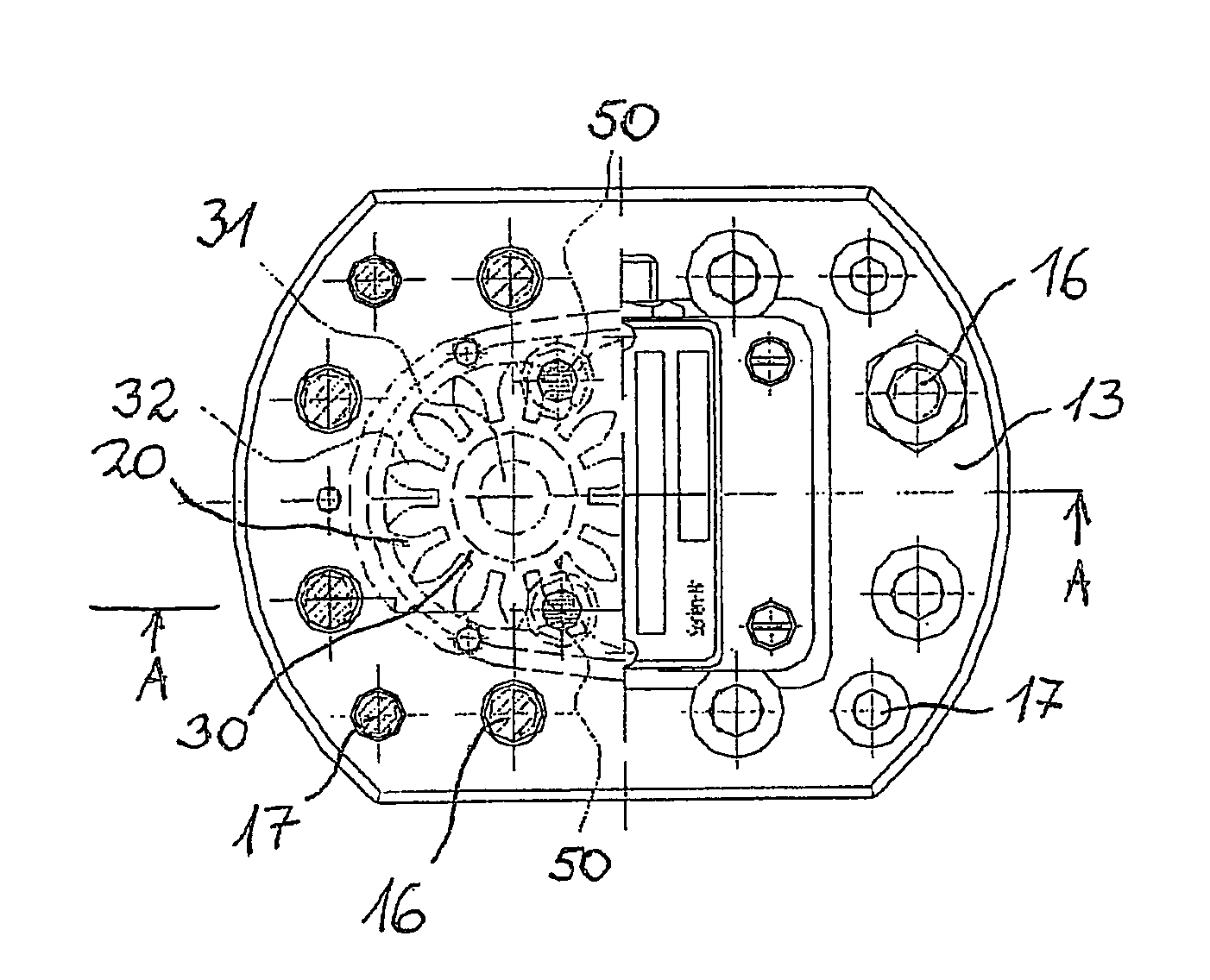
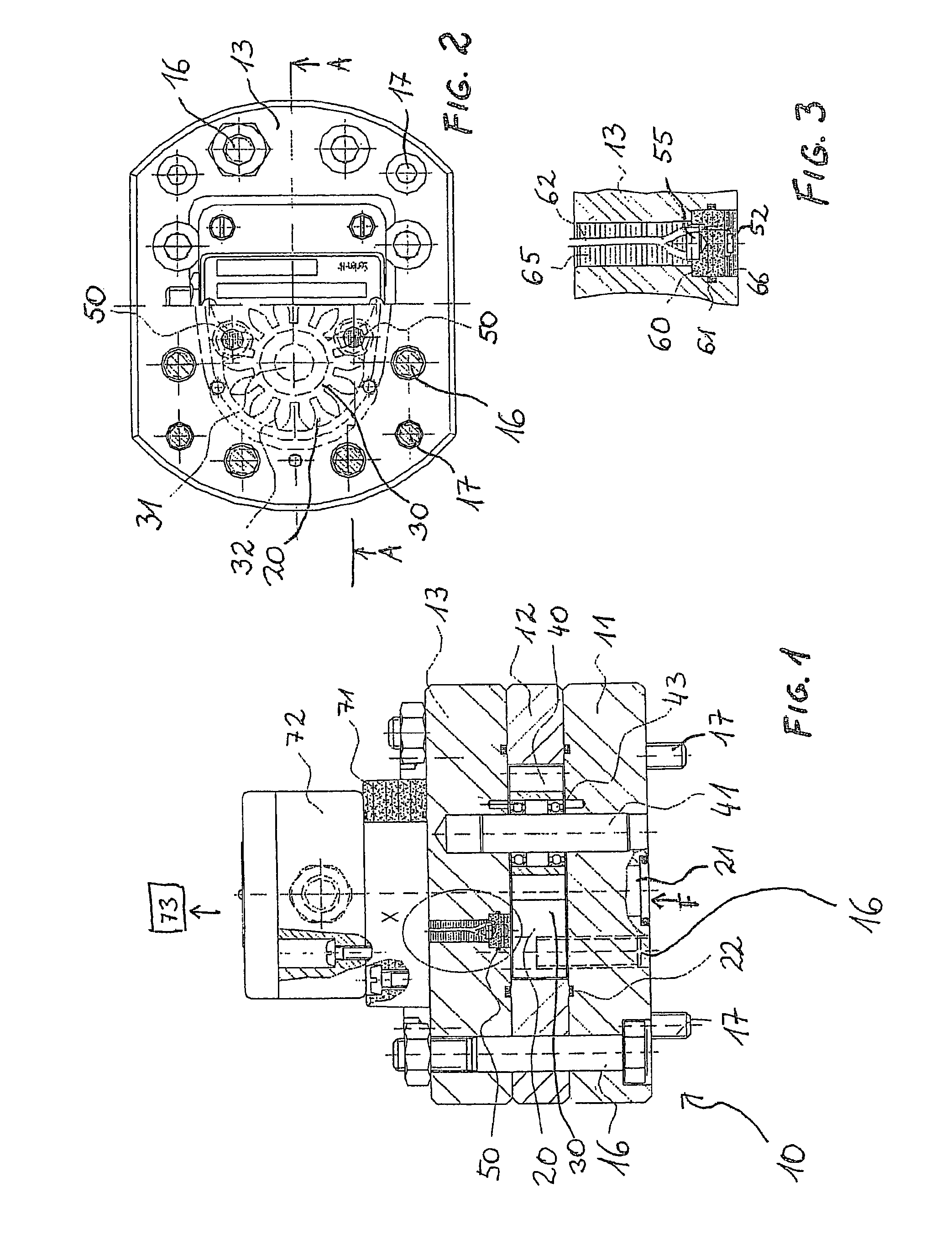
[0048]FIG. 1 shows as an overview a section through a flow rate instrument according to the invention. The section does not extend in an exact plane but is offset forward and backward several times in order better to show the details of the flow rate instrument. The more exact line direction of the forward and backward offsets may be gathered from FIG. 2.

[0049]Particularly evident is a housing 10 of the flow rate sensor. The housing 10 comprises in particular three plate-like elements laid one on top of the other, namely a base plate 11, a middle piece 12 and a cover 13. In this case, the base plate 11 and the middle piece 12, taken together, are roughly comparable to the first housing half mentioned in the background art in DE 40 42 397 C2.

[0050]The base plate 11, the middle piece 12 and the cover 13 are connected to one another by fit bolts 16 as well as fastening screws 17. This connection has to be very precise, on the one hand, and very strong, on the other hand, because a meas...


PUM


Abstract

The invention relates to a flow sensor having a measuring chamber to which a fluid whose volume and / or rate of flow is to be measured is supplied and then drawn off. Inside the measuring chamber elements of a measuring mechanism are mounted so as to freely rotate. The sensor is also provided with a magnet which produces a magnetic field inside the measuring chamber and in close proximity thereto. At least one sensor device measures the magnetic field and / or changes in the magnetic field. The sensor device for measuring the magnetic field is provided with at least one giant magnetoresistance sensor.

Description

TECHNICAL FIELD[0001]The invention relates to a flow rate sensor having a measuring chamber, into which a fluid, the volume and / or flow rate of which is to be measured, can be fed and then discharged, having measuring mechanism elements disposed in the measuring chamber and mounted in a freely rotatable manner, having a magnet for generating a magnetic field in the measuring chamber and in the immediate vicinity thereof, and having at least one sensor device for measuring the magnetic field and / or variations of the magnetic field.BACKGROUND OF THE INVENTION[0002]Flow rate sensors are also known as volume sensors. Generally, they take the form of displacement meters. Examples of these are gear sensors, screw spindle meters, oval-wheel meters, cylindrical-piston meters or alternatively measuring turbines or proportioning gear pumps. They are used to measure a volume, a throughflow quantity or the rate at which a medium, here therefore a fluid, passes through the measuring instrument. ...

Claims


Application Information

Patent Timeline
IPC IPC(8): G01F15/00G01D5/16G01F3/10G01R33/09
CPCG01F3/10
Inventor ERTLER, WERNER
Owner VSE VOLUMENTECHNIK GMBH
Why Eureka
Try Eureka