Battery powered concrete saw

a battery-powered concrete and sawing technology, which is applied in the direction of manufacturing tools, roads, construction, etc., can solve the problems of time required to run an electrical line, prohibitively expensive, and not being able to meet the requirements of heavy-duty concrete cutting jobs,

Active Publication Date: 2011-05-17
GOBRIGHT IV FRANCIS M
View PDF24 Cites 11 Cited by
  • Summary
  • Abstract
  • Description
  • Claims
  • Application Information

AI Technical Summary

Benefits of technology

[0009]In carrying out the above object, a concrete cutting saw constructed in accordance with the present invention includes a frame having a pair of rear wheels and a pair of front wheels for facilitating movement of the saw to different locations for use and for movement during a cutting operation. An electric motor of the saw is of at least 5 horsepower and is mounted by the frame. The frame also has a mounting arrangement for supporting a battery pack for operating the electric motor. A battery powered transmission drives the rear wheels to provide self-propulsion of the saw. A pair of saw arbors are respectively mounted for rotation on opposite lateral sides of the frame forward of the pair of front wheels, and the saw arbors have a rotational connection to the electric motor to provide rotational driving of the saw arbors for cutting. An actuator moves the front wheels upwardly and downwardly with respect to the frame to pivot the frame about the rear wheels between an upper idle position and a lower use position that permits cutting of concrete or the like with a saw blade mounted on one of the arbors.
[0014]The concrete saw also includes a pair of blade guards respectively associated with the pair of saw arbors to provide protection from a saw blade mounted on either arbor.

Problems solved by technology

However, when indoor cutting is required, the generator due to the exhaust generated must be operated outside and the time required to run an electrical line, which often is hundreds of feet and / or up a number of stories, can be prohibitedly expensive.
This engraver is manually moved much like a carpet vacuum cleaner and does not appear to be sufficiently heavy duty to permit use in heavy duty concrete cutting jobs.
The necessity for spaced tracks for such a concrete cutter would result in any cutting job also being prohibitedly expensive.

Method used


Image

  • Battery powered concrete saw
  • Battery powered concrete saw
  • Battery powered concrete saw

Examples


Embodiment Construction

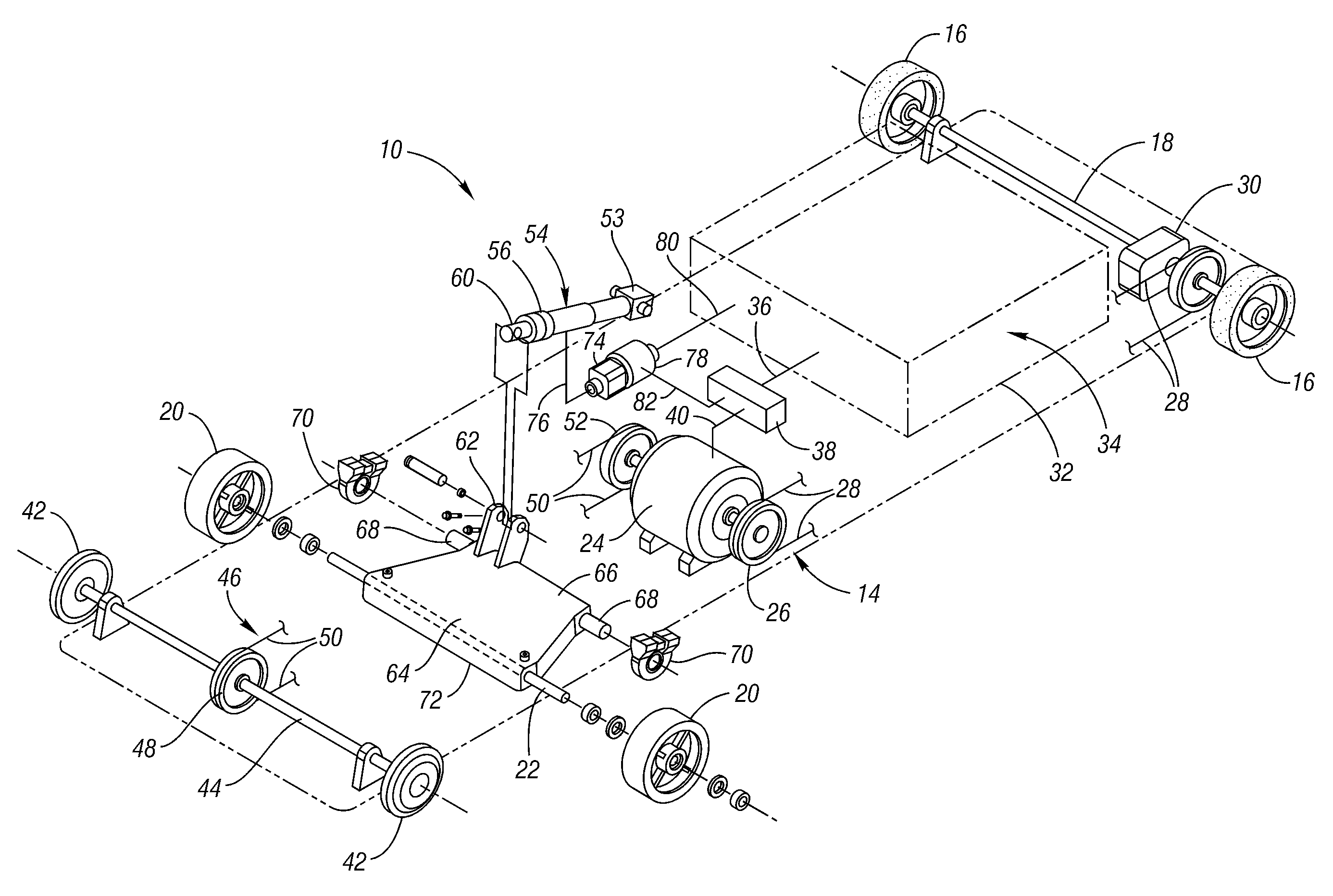
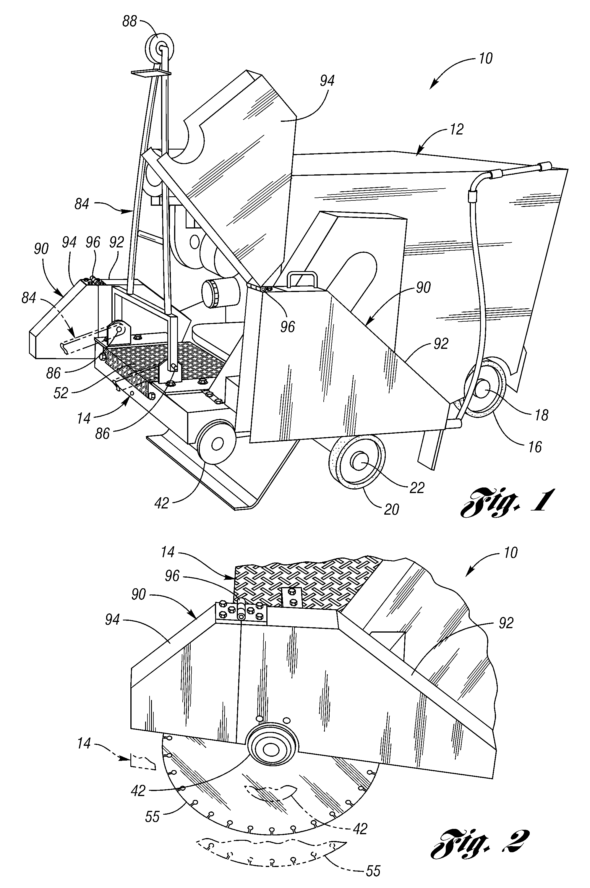
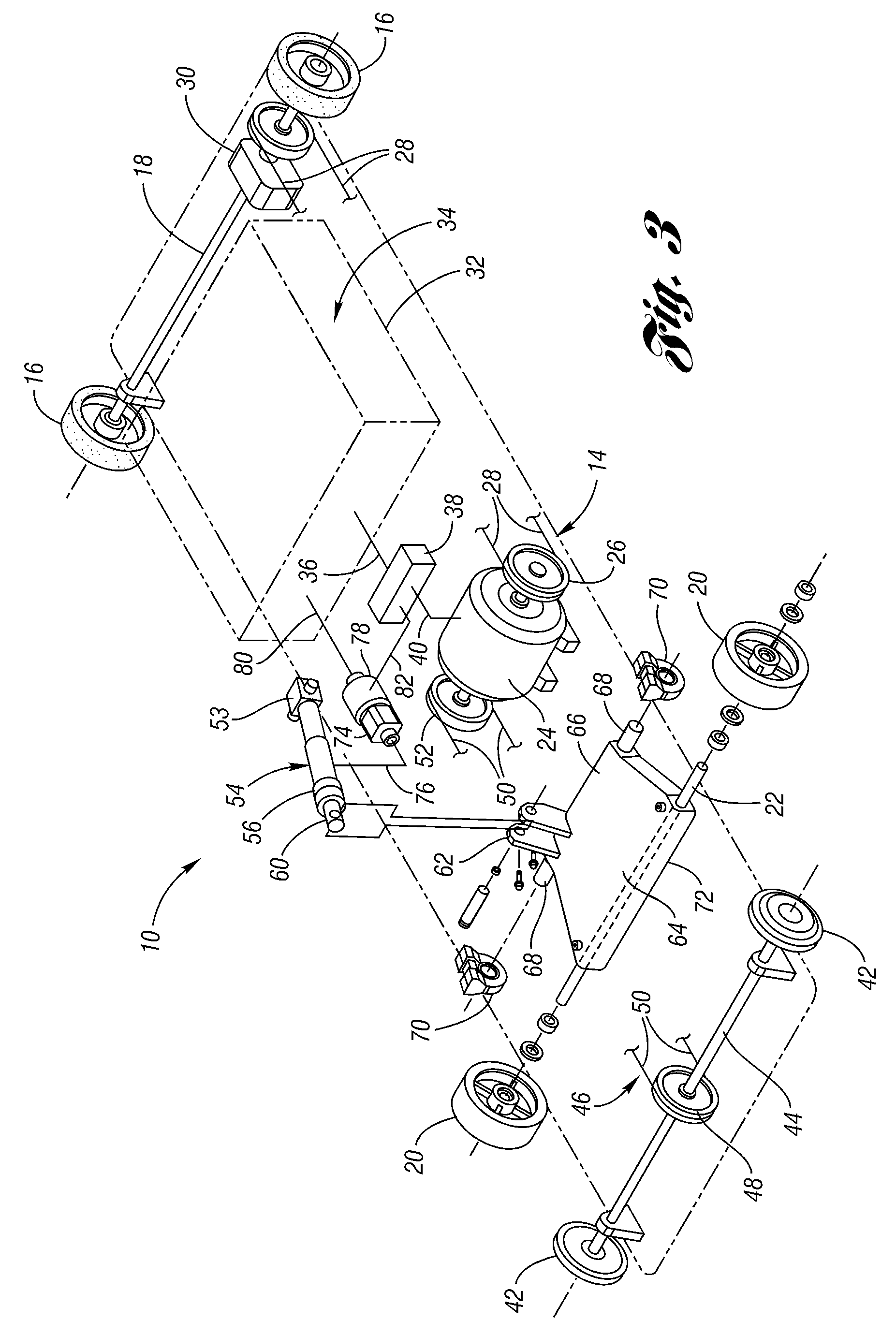
[0019]With reference to FIG. 1 of the drawings, a concrete saw 10 is constructed to cut concrete, asphalt and the like as is hereinafter more fully described. This concrete saw includes a housing 12 that may be fabricated from sheet metal or molded plastic, etc. The concrete saw 10 as shown in FIG. 3 includes a frame 14 having a pair of rear wheels 16 that are supported by an axle 18 on the frame. A pair of front wheels 20 are also supported on the frame by an axle 22 as is hereinafter more fully described. The rear wheels 16 and front wheels 20 cooperate to facilitate movement of the concrete saw 10 to different locations for use and for movement during a cutting operation.

[0020]As shown in FIG. 3, an electric motor 24 is mounted on the frame 14 and has a rotary output 26 that drives a belt or chain 28 which drives a rotary input 29 to a hydrostatic transmission 30 that drives the rear wheel axle 18 to provide self propulsion of the saw during transport between cutting locations an...


PUM

PropertyMeasurementUnit
cutting poweraaaaaaaaaa
currentaaaaaaaaaa
currentaaaaaaaaaa

Abstract

A concrete saw (10) has an electric motor (24) energized by a battery pack (34) to drive a pair of saw arbors (42) and a battery powered transmission (30) drives rear wheels (16) that provide self propulsion of the saw in cooperation with front wheels (20). A power operated actuator (54) raises and lowers the front wheels (20) to provide upward and downward movement of the saw frame (14) about its rear wheels (16). The battery pack (34) may be lead acid batteries, nickel-cadmium batteries, nickel metal hydride batteries or lithium batteries, and the electric motor (24) has 5 to 15 horsepower, preferably about 10 horsepower, to provide cutting of most conventional concrete jobs.

Description

BACKGROUND OF THE INVENTION[0001]1. Field of the Invention[0002]This invention relates to a battery powered concrete saw for cutting concrete, asphalt and the like, etc.[0003]2. Background Art[0004]Saws for cutting concrete, asphalt and the like, etc. are conventionally electrically powered or powered by an internal combustion engine that utilizes gasoline or diesel fuel, the latter of which cannot be used indoors due to the exhaust generated. When concrete saws are powered by electricity, an internal combustion engine generator is conventionally used because 240 or 480 volt 3 phase power is required to operate concrete saws of about 5 horsepower or more. However, when indoor cutting is required, the generator due to the exhaust generated must be operated outside and the time required to run an electrical line, which often is hundreds of feet and / or up a number of stories, can be prohibitedly expensive.[0005]U.S. Pat. No. 7,000,605 Due discloses a concrete engraver apparatus and met...

Claims


Application Information

Patent Timeline
Patent Type & Authority Patents(United States)
IPC IPC(8): B28D1/24
CPCE01C23/0933B28D1/045
Inventor GOBRIGHT, IV, FRANCIS M.
Owner GOBRIGHT IV FRANCIS M
Why Eureka
Try Eureka