Adjustable damping control with end stop

a damping control and adjustable technology, applied in the direction of shock absorbers, mechanical equipment, transportation and packaging, etc., can solve the problems of affecting the operation of the vehicle, and the end stops themselves tend to be very abrupt and uncomfortable for the operator

Inactive Publication Date: 2011-05-17
LORD CORP
View PDF21 Cites 46 Cited by
  • Summary
  • Abstract
  • Description
  • Claims
  • Application Information

AI Technical Summary

Problems solved by technology

Over time, these conditions may lead to dangerous vehicle operation, fatigue, lower-back pain, osteoarthritis and leg discomfort.
Under certain conditions, some or all of these conventional suspension systems provide little transition into the end stops, and the end stops themselves tend to be very abrupt and uncomfortable for the operator.
However, if the system velocity is high enough when an end stop collision occurs, a very rapid impact may result.
This bottoming or topping imparts unwanted stresses to the mechanical components in the system (e.g. linkages, swing arms, bushings, joints, etc.), is detrimental to the system's overall life, can be an annoyance to the seat occupant, and may effect the physical health of the seat occupant.
More significantly, when a vehicle operator experiences an end stop collision, the motion in the seat may lead to a loss of control of the vehicle.
Soft passive dampers provide smooth mid-ride performance but leave the seat occupant vulnerable to the uncomfortable and possibly harmful effects of topping and bottoming during unexpected large vibration inputs.
Firm passive dampers, on the other hand, may minimize topping and bottoming, but mid-ride performance is compromised.
However, there is no form of end stop control.

Method used


Image

  • Adjustable damping control with end stop
  • Adjustable damping control with end stop
  • Adjustable damping control with end stop

Examples


Embodiment Construction

[0029]As required, detailed embodiments of the present invention are disclosed herein, however, it is to be understood that the disclosed embodiments are merely exemplary of the invention that may be embodied in various and alternative forms. Specific structural and functional details disclosed herein are not to be interpreted as limiting, but merely as a basis for the claims as a representative basis for teaching one skilled in the art to variously employ the present invention. Throughout the drawings, like elements are given like numerals. The damping control methods and systems described below apply to seating applications, however, in principle also apply to any non-seating application requiring a high-function damping system.

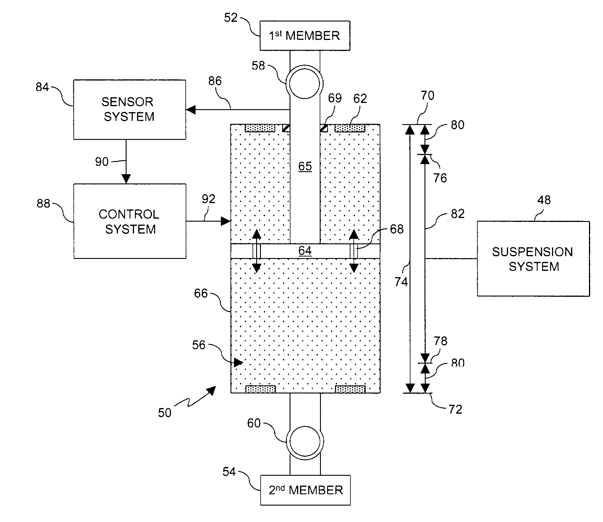
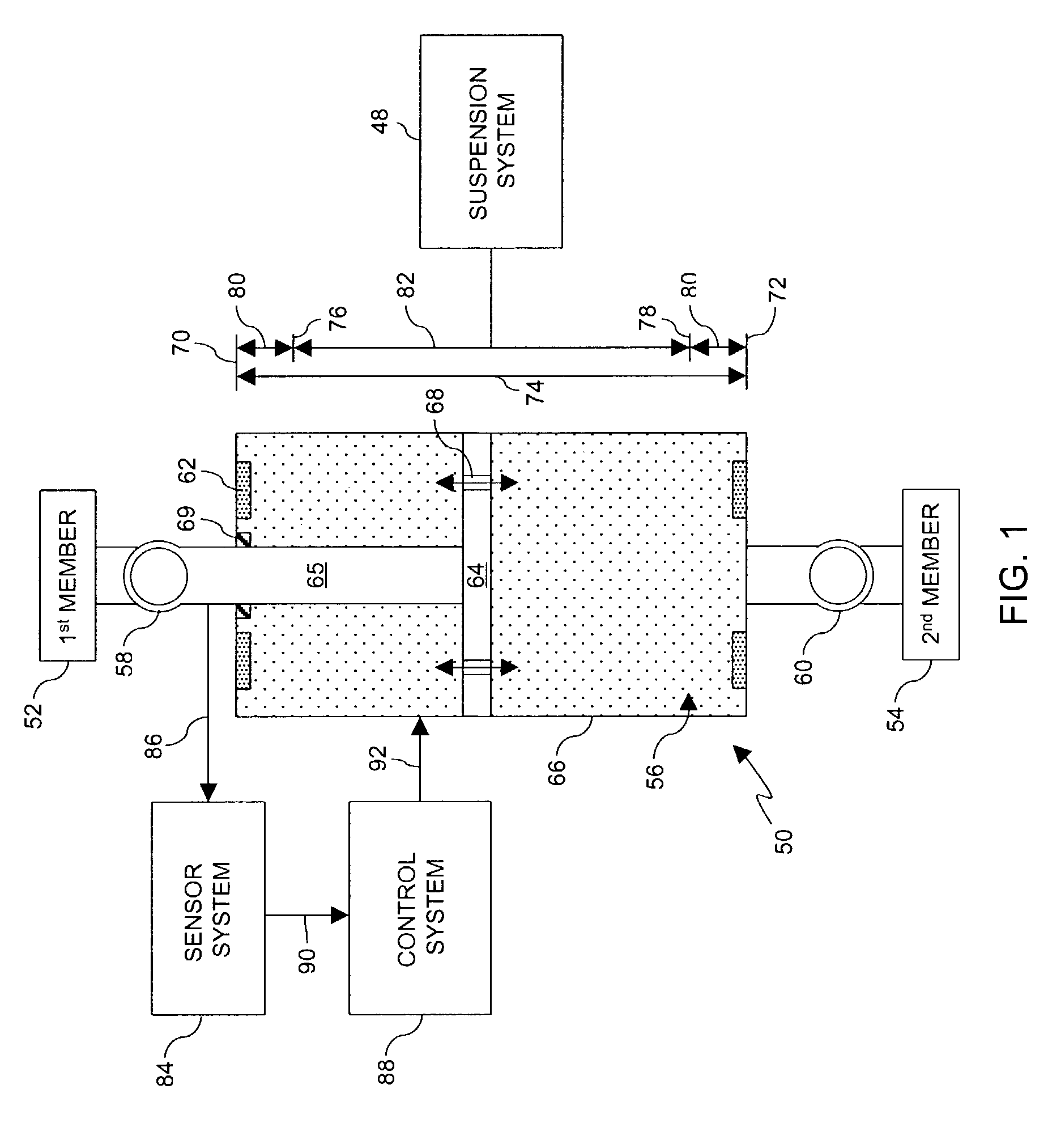
[0030]Referring now to FIG. 1, the suspension system 48 being controlled generally includes an electro-mechanical damping device 50 that is attached between a first structural member 52 and a second structural member 54. The electro-mechanical damping devic...


PUM


Abstract

A damper device comprising a first mode having a first level of damping, a second mode having a second level of damping corresponding to a predetermined function, a sensor system having a first output corresponding to a normal position and a second output corresponding to an end stop approaching position, and a control system operable for receiving the first output and the second output and executing the first mode and the second mode. The damper device is operable in the first mode when the control system receives the first output and is operable in the second mode when the control system receives the second output. A controllable suspension system comprising a damper device, a magnetic probe, a sensor system comprising at least one position sensor operable for sensing the position of the magnetic probe, and a control system electronically connected to the sensor system and the damper device, wherein the control system is operable for receiving an output from the sensor system and executing a predetermined function to control the damper device. Electric signals are supplied to the damper device from the control system during system operation to provide damping sufficient to prevent end stop collisions.

Description

CROSS-REFERENCE TO RELATED APPLICATIONS[0001]United States Utility Patent Application by Marjoram et al., entitled “MAGNETORHEOLOGICAL TWIN-TUBE DAMPING DEVICE” filed the same day as the present Application is related and hereby incorporated by reference.BACKGROUND OF THE INVENTION[0002]1. Field of the Invention[0003]The present invention relates generally to the field of suspension devices. More particularly, the present invention relates to control systems and methods that utilize a specially tuned damper, controller, and sensor to trigger an end stop function.[0004]2. Description of the Related Art[0005]In vehicle use, vibrations, shock, and motion resulting from uneven road surfaces are transferred to a vehicle operator through the operator's seat. Over time, these conditions may lead to dangerous vehicle operation, fatigue, lower-back pain, osteoarthritis and leg discomfort. Typically, seats used in commercial and public transportation vehicles, such as trucks and buses, includ...

Claims


Application Information

Patent Timeline
Patent Type & Authority Patents(United States)
IPC IPC(8): F16F9/53B60N2/52F16F9/46F16F9/48F16F9/58
CPCB60N2/501B60N2/502B60N2/505B60N2/508B60N2/527F16F9/46F16F9/48F16F9/58B60N2/522F16F2230/08B60N2/50
Inventor ST. CLAIR, KENNETH A.BOONE, KENNETH R.IVERS, DOUGLAS E.
Owner LORD CORP
Why Eureka
Try Eureka