
Bend limiting boot

a technology of limiting boots and limiting lugs, applied in the field of limiting boots, can solve the problems of fiber breakage, signal loss, further signal degradation, etc., and achieve the effect of delicate optical components

Inactive Publication Date: 2011-05-17
TE CONNECTIVITY CORP
View PDF9 Cites 9 Cited by
  • Summary
  • Abstract
  • Description
  • Claims
  • Application Information

AI Technical Summary

Benefits of technology

The present invention provides a non-pull proof connector that allows for easy mating without damaging delicate optical components. The connector has a boot that is secured to the housing, rather than the ferrule assembly, which prevents any force from being applied to the ferrule assembly during mating. The boot allows for backward movement of the ferrule assembly relative to the boot, which further protects the optical components. The connector also includes a spring that biases the ferrule assembly forward in the housing. Overall, this design ensures a safe and reliable connection between optical components.

Problems solved by technology

A sharp bend (i.e., small radius) in a fiber can lead to signal loss by virtue of at least some of the transmitted light leaking out of the fiber at the bend.
A sharp bend can also cause further signal degradation if the bend introduces microcracks in the fiber, which reduce or impair the uninterrupted guiding of the optical signals.
An excessively sharp bend may even cause fiber breakage.
Although connector 300 has performed well over the years, recently, Applicants have recognized a trend that connectors used with active components and in backplane applications have a disproportionately high failure rate, especially when used in high-density applications.
These failures are caused, in general, by damaged optical components within the mating devices.
Noteworthy is the fact that this high failure rate is associated with mating devices having “fixed” optical interfaces, such as fixed ferrules used in transceivers and backplane connectors.
Applicants surmised that these failures occur more frequently in high-density connector applications because installers use the boot to push the connector forward to effect mating.
That is, in such high density applications, there is insufficient room around the connector for an installer to grasp the housing and push it forward such that the connector engages and mates with the mating device.
Accordingly, pushing the connector forward into a mating device having a fixed optical interface may result in much higher than expected mating force because the optical components of the fixed optical interface cannot “backup” in response to higher than expected mating forces.
The pressure between the ferrule assembly and these optical components can increase significantly, possibly resulting in damage to either the connector, the mating structure, or both.
In addition to causing damage to the optical components, Applicants also recognize that using the boot to push a non-pull proof connector forward to mate tends to be ineffective.
Additionally, because the ferrule assembly 301 is biased forward in the housing 302, this biasing actually urges the housing backward away from the mating device, thereby making contact between the housing 302 and the mating device even more difficult.

Method used


Image

  • Bend limiting boot
  • Bend limiting boot
  • Bend limiting boot

Examples


Embodiment Construction

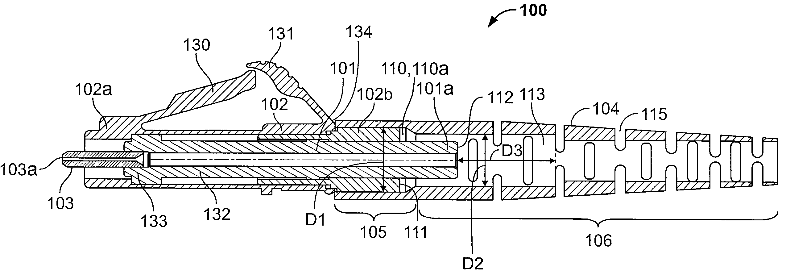
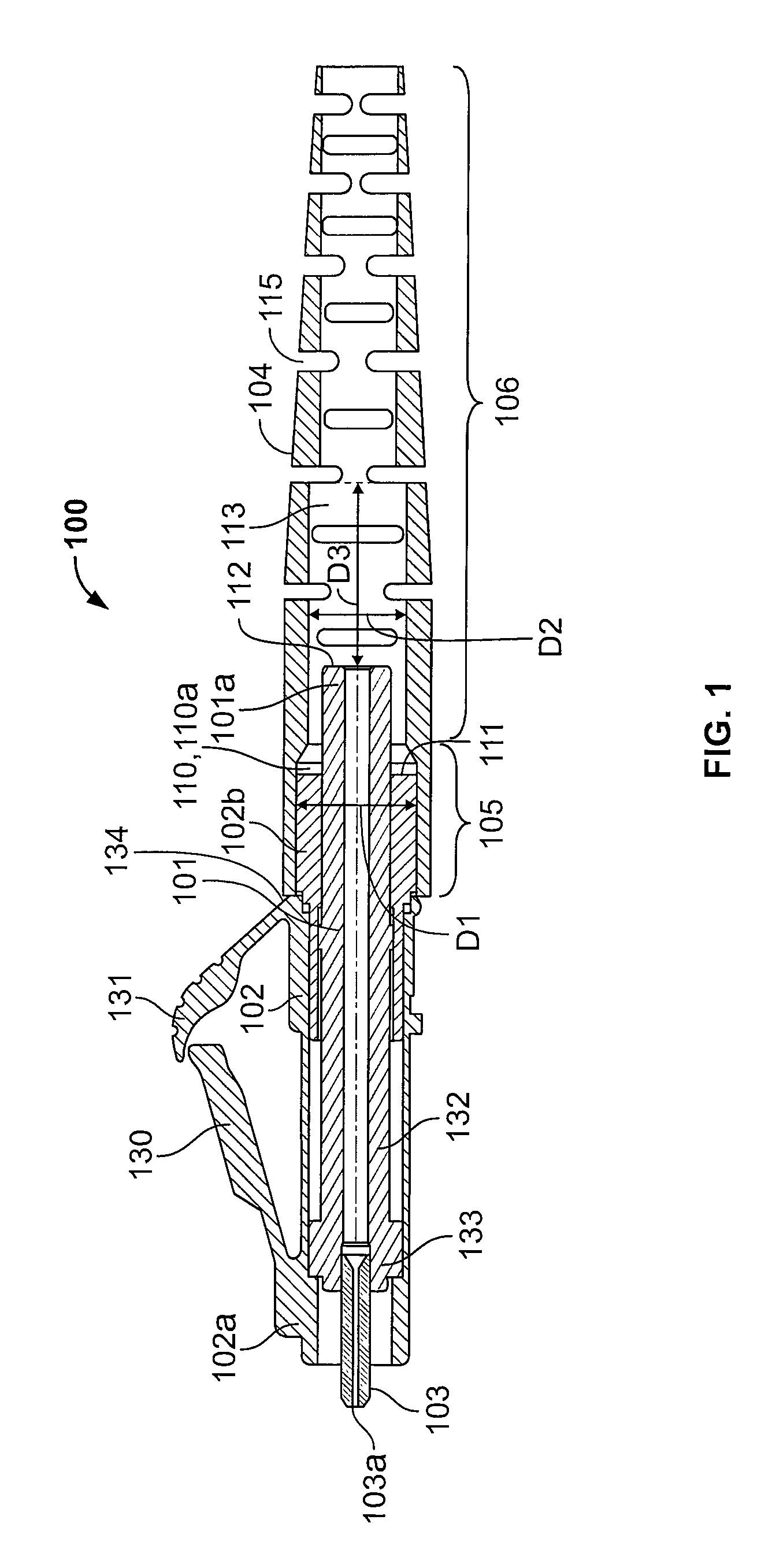
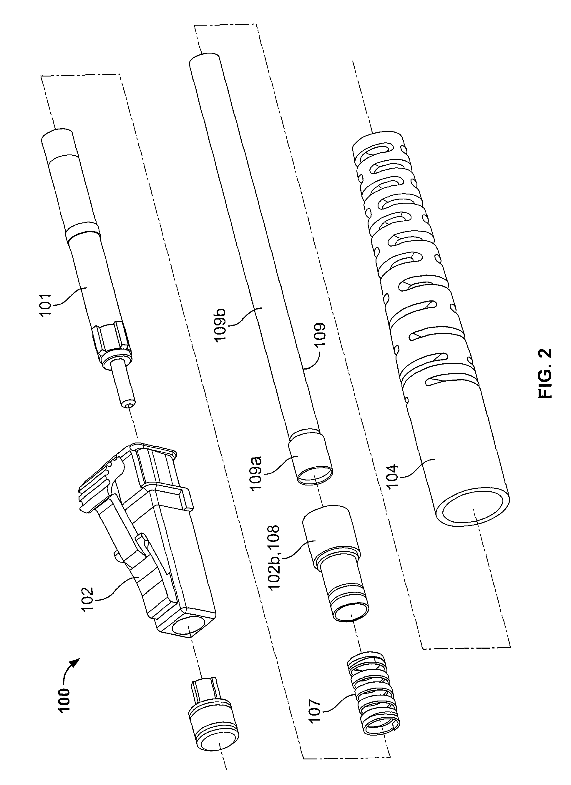
[0016]Referring to FIGS. 1 and 2, one embodiment of a connector 100 of the present invention is shown. As shown, the connector 100 has a front and back orientation and comprises the following: (a) a cable (not shown) having at least a jacket and an optical fiber; (b) a ferrule assembly 101 comprising a rear portion 101a for attachment to the jacket, and a ferrule 103 defining a bore hole 103a for holding the fiber; (c) a housing 102 having a front portion 102a configured for mating with a mating structure and a back portion 102b configured for attachment to a boot 104; (d) a spring 107 biasing the ferrule assembly 101 forward in the housing 102; and (e) the boot 104 secured to the back portion of the housing 102 and extending rearward around the cable, the boot having an internal channel 113 large enough to allow for relative movement of the ferrule assembly 101.

[0017]The particular connector disclosed in FIGS. 1 and 2 is a non-pull proof, LC-type connector, which is a small form fa...


PUM


Abstract

A connector having a front and back orientation and comprising: (a) a cable having at least a jacket and an optical fiber; (b) a ferrule assembly comprising a rear portion for attachment to said jacket, and a ferrule defining a bore hole for containing said optical fiber; (c) a housing having a front portion configured for mating with a mating structure and a back portion configured for attachment to a boot; (d) a spring biasing said ferrule assembly forward in said housing; and (e) a boot secured to said back portion of said housing and extending rearward around said tight-jacketed cable, said boot having an internal channel large enough to allow axial movement of said ferrule assembly relative to said boot.

Description

FIELD OF INVENTION[0001]The present invention relates generally to bend limiting boots for optical connectors and, more specifically, to bend limiting boots for non-pull proof connectors.BACKGROUND OF INVENTION[0002]Optical fiber connectors are an essential part of practically all optical fiber communication systems. For instance, such connectors are used to join segments of fiber into longer lengths, to connect fiber to active devices such as radiation sources, detectors and repeaters, and to connect fiber to passive devices such as switches and attenuators. The principal function of an optical fiber connector is to optically couple a fiber with an optical pathway of a mating device (e.g., another fiber, an active device or a passive device) by holding the end of the fiber, typically in a ferrule, such that the core of the fiber is axially aligned with the optical pathway of the mating device.[0003]Optical connectors may be classified as either pull-proof or non-pull proof. In a pu...

Claims


Application Information

Patent Timeline
Patent Type & Authority Patents(United States)
IPC IPC(8): G02B6/38
CPCG02B6/3887G02B6/38875G02B6/3888
Inventor HOPKINS, ERIC JAMESBRIGGS, ROBERT CARLMILLER, STEPHEN JAMES
Owner TE CONNECTIVITY CORP
Learn More