Wearable device

a wearable device and technology of a smart watch, applied in the field of wearable devices, can solve the problems of not being able to miniaturise the components required for unlocking and/or operating a vehicle in a sufficient degree to allow their incorporation within the casing of the smart watch, and not being able to achieve the effect of maintaining the flexibility of the circuit board

Active Publication Date: 2021-02-04
ARMOR SURVEILLANCE SECURITY EQUIP & TECH LTD
View PDF0 Cites 1 Cited by
  • Summary
  • Abstract
  • Description
  • Claims
  • Application Information

AI Technical Summary

Benefits of technology

[0028]In an embodiment, the flexible circuit board is conformally coated. Advantageously, this protects the circuit board from ingress of moisture and dirt, whilst maintaining the flexibility of the circuit board.
[0029]In an embodiment the cell is potted within a cell housing. Advantageously, this protects the cell board from ingress of moisture and dirt
[0030]In an embodiment, the substantially metal watch housing is waterproof. This protects the delicate components of the mechanical watch movement from moisture and dirt.

Problems solved by technology

However, the commercially-available smart watches mentioned above typically do not incorporate the functionality to communicate with vehicle security systems that provide remote unlocking and / or activation of a vehicle.
This may be because miniaturisation of the components required for unlocking and / or operating a vehicle to a sufficient extent to allow their incorporation within a casing of a smart watch has not yet been possible.
In contrast to the electronic devices mentioned above, analogue watches typically only provide the functionality to tell the time via a clock face, with additional functions generally limited to a display of the day and date, and additional stopwatch features.
Because mechanical movements do not incorporate electronic components, miniaturisation is limited compared to electronically-controlled components.
Miniaturisation of mechanical watch movements is particularly challenging if the movement is to incorporate stopwatch and / or date display features, as these features require the movement to be provided with additional mechanical complications, which can increase the overall package size required.
Because mechanical watch movements typically occupy a lot of space, it has hitherto proved difficult to combine a mechanical watch with other features that it may be desirable to provide within a wearable device.

Method used


Image

  • Wearable device
  • Wearable device
  • Wearable device

Examples


Embodiment Construction

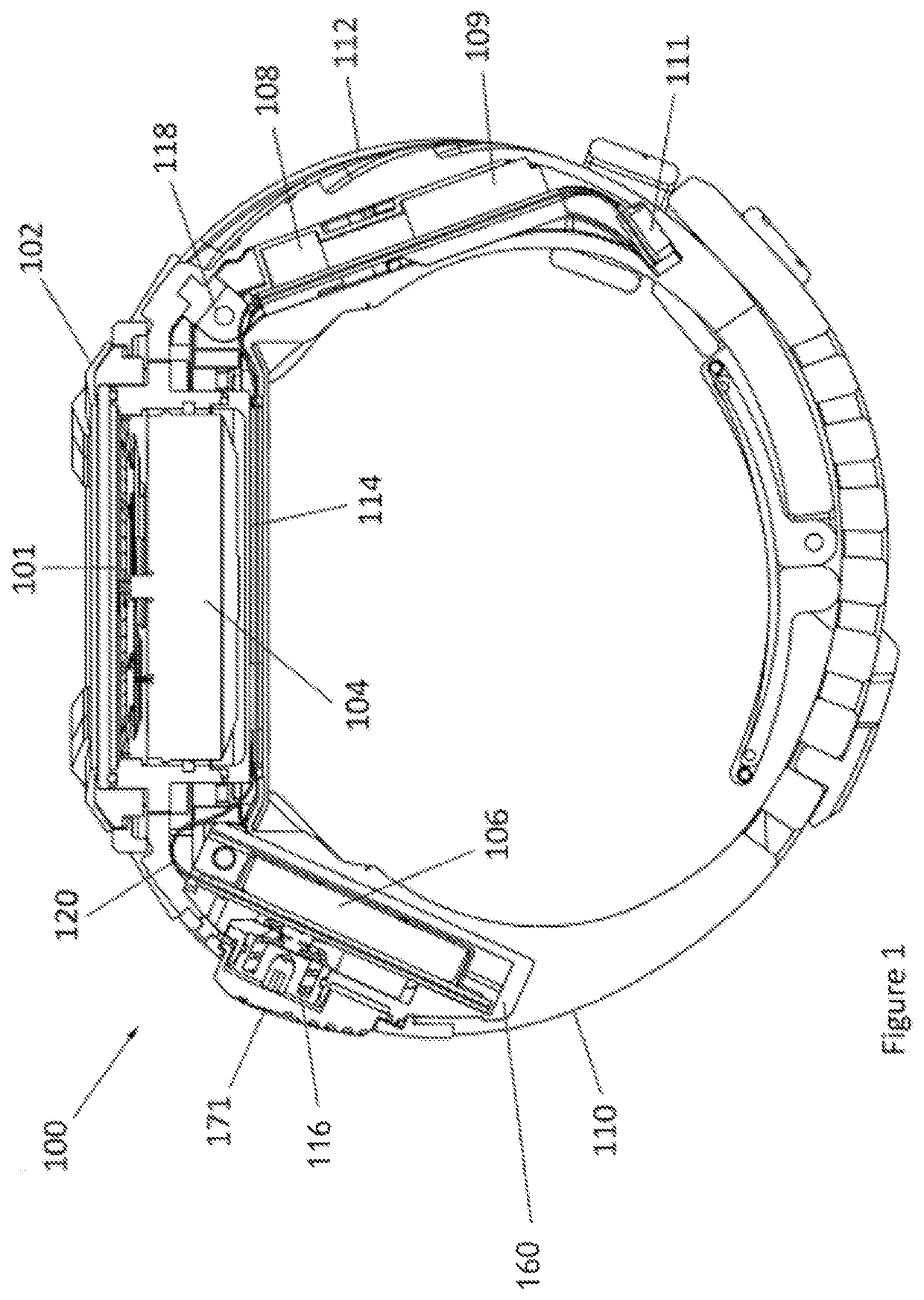
[0051]FIG. 1 shows a cross section through a wearable device 100 according to an embodiment of the present invention. The wearable device combines the functionality of a conventional mechanical watch with apparatus for communicating with a remote security system. Although the present invention may have other applications, the invention will be described with particular reference to embodiments in which the security system is a remote security system of a vehicle, such as a keyless entry or a keyless go system.

[0052]The wearable device comprises first and second straps 110,112, which are each connected to opposite ends of a watch housing 102, which contains a mechanical watch movement 104. The watch movement is a conventional mechanical watch movement that controls several components including the hands of the watch face 101. In the illustrated embodiment, the watch movement also provides a stopwatch function and a date display function. However, it will be understood that a differen...


PUM


Abstract

The present invention provides a wearable device comprising a mechanical watch movement located within a watch housing, and first and second straps connected to the watch housing, such that the device is suitable for wearing on a user's wrist. The first strap has a coin cell located in a cavity, and the second strap has a first electronic communication device located in a cavity. The coin cell and the electronic communication device are connected by a flexible circuit board. Advantageously, this may provide a wearable device having the functionality to interact with a remote security system of a vehicle, such as a keyless entry system or a keyless go system.

Description

TECHNICAL FIELD[0001]The present disclosure relates to a wearable device. In particular, but not exclusively, the disclosure relates to a wearable device having the functionality to act as a wireless key for a vehicle.BACKGROUND[0002]Wrist-wearable devices are very widely used and may broadly be categorised as either “electronic” or “analogue” devices. Electronic wearable devices have recently gained popularity. Such devices include smart watches, which typically include a touch screen controlled by a processor. In addition to telling the time, smart watches may also communicate with external devices via wireless communication protocols such as Bluetooth (RTM), and they may provide various additional functions similar to those performed by a modern smartphone, albeit on a much smaller screen.[0003]One other type of electronic wearable device having current applicability is a remote key fob that constantly (or intermittently or selectively) generates a weak radio signal capable of be...

Claims


Application Information

Patent Timeline
Patent Type & Authority Applications(United States)
IPC IPC(8): H04B1/3827G04G21/04G04G17/08G04G17/04B60R25/24B60R25/01
CPCH04B1/385G04G21/04G04G17/08H05K1/0278B60R25/245B60R25/01G04G17/04G07C9/00309G07C9/00944G07C2009/00968G06K19/07762G07C9/20H05K3/4691H05K1/189H05K3/284H05K2201/09872A44C5/00G04B47/005G07C9/00174G06F1/16
Inventor DINAN, RICHARDFAWCETT, PATRICK JAMES
Owner ARMOR SURVEILLANCE SECURITY EQUIP & TECH LTD
Why Eureka
Try Eureka