Lens driving device

a driving device and electromagnetic technology, applied in the direction of dynamo-electric components, dynamo-electric machines, instruments, etc., can solve the problems of inability to support the resolution performance of image sensors with a large amount of pixels, decrease of the driving magnetic field generated by permanent magnets, and out-of-focus problems, so as to achieve the effect of further improving the sensitivity of displacement and displacemen

Active Publication Date: 2011-05-17
MICRO WIN TECH +2
View PDF4 Cites 0 Cited by
  • Summary
  • Abstract
  • Description
  • Claims
  • Application Information

AI Technical Summary

Benefits of technology

[0017]In order to maintain the distribution of the driving magnetic field intersecting with the driving coil, an initial position of the driving coil is located at a place where the magnitude of the driving magnetic field intersecting with the driving coil is in the range of 50%˜90% of the maximum value, to provide appropriate offset, improve the linearity of driving current versus displacement, and obtain higher displacement sensitivity.
[0018]Furthermore, the present invention is characterized in that the polarity of the permanent magnets at a side close to the lens holder is either all N-polarity, or all S-polarity. In this way, the configuration of the permanent magnets may be simplified.
[0020]In this way, the demagnetized field of the permanent magnets may be weakened, and the linearity of driving current vs. displacement and displacement sensitivity may be further improved.
[0022]In such configuration, the demagnetized field may be weakened, and the linearity of driving current vs. displacement may be further improved. Also, such a configuration only requires one driving coil, which simplifies the structure of the lens driving device.

Problems solved by technology

This is because the fixed-focal type camera modules may suffer serious out-of-focus problem and be unable to support the resolution performance of the image sensor with a large amount of pixels.
However, in order to advance the low-profiling and radial miniaturization of the lens driving device, the tendency is to shrink the height and thickness of the permanent magnet 52, which this, in turn, results in the decrease of the strength of driving magnetic field generated by the permanent magnet 52, and also makes it more difficult to place the driving coil 55 in the uniform magnetic field.
Moreover, in order to advance the low-profiling and radial miniaturization of the lens driving device, it may be difficult to obtain sufficient offset among the fulcrums of the spring members 57A, 57B.
In addition, the driver of the lens driving device is not configured to accommodate with the characteristics of most existing lens driving device.
It is difficult to significantly change the value of the initial current A in prior art.

Method used


Image

  • Lens driving device
  • Lens driving device
  • Lens driving device

Examples


first embodiment

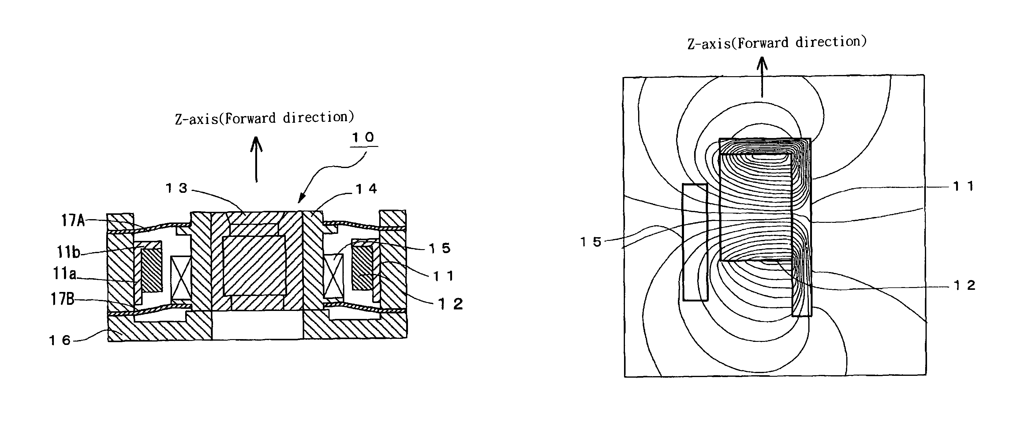
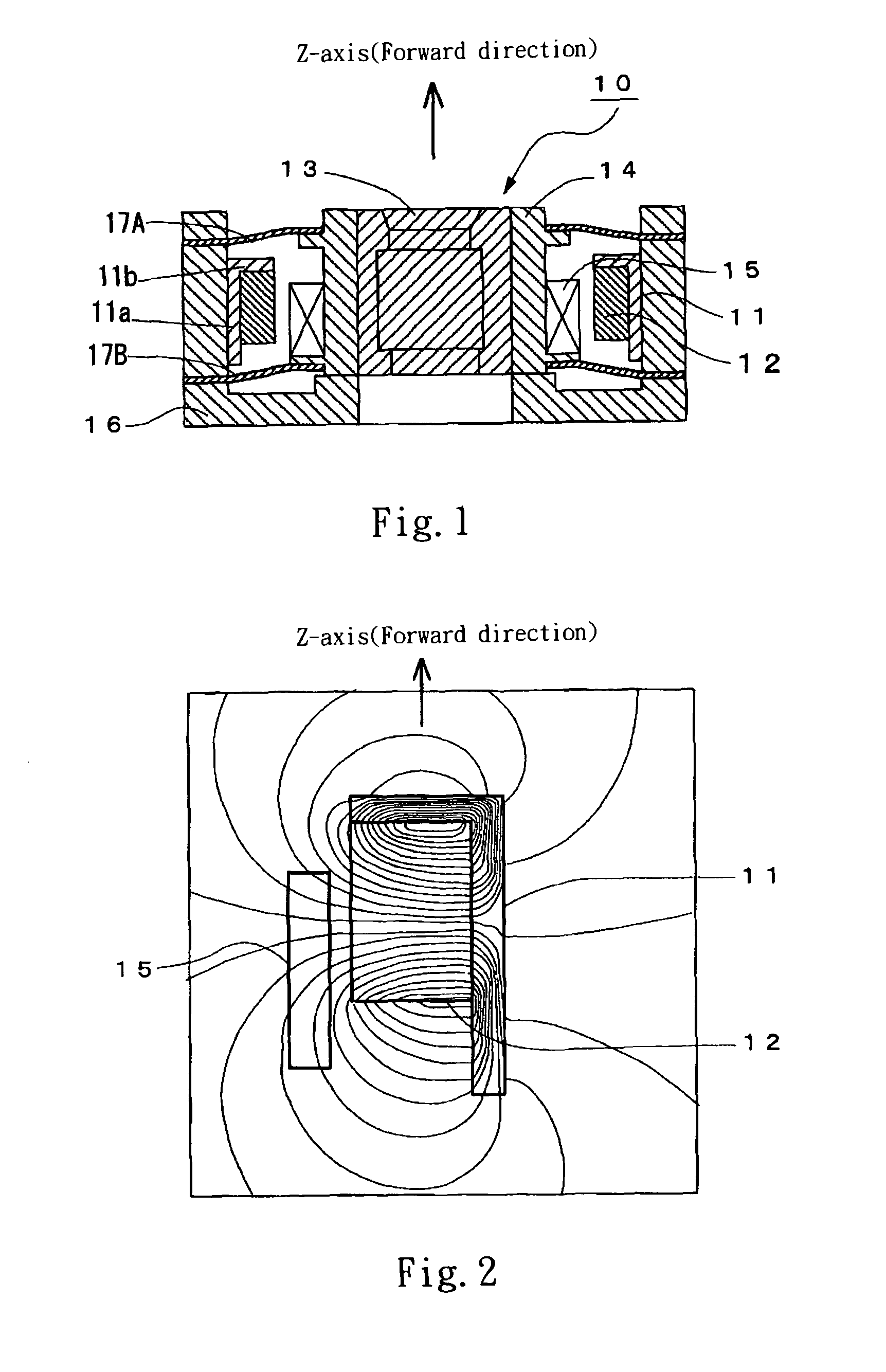
[0037]FIG. 1 is a cross-section view of the lens driving device in accordance with the first embodiment of the present invention.

[0038]The lens driving device 10 is provided with: a yoke 11 made of magnetic substance, such as soft iron, a permanent magnet 12 mounted on an inner sidewall of the yoke 11, a lens set 13 constructed by at least one object lens and at least one ocular lens, a lens holder 14 for holding the lens set 13 at a center position, a driving coil 15 mounted on an outer sidewall of the lens holder 14, a casing 16 whose inner circumference being provided with the yoke 11, and an upper spring member 17A and a lower spring member 17B connecting the casing 16 and the lens holder 14.

[0039]Furthermore, the up-and-down direction in the present invention is the direction parallel to the optic axis of the lens set 13. The upper side of FIG. 1 is the side of the imaged object (not shown). In addition to the naming of the spring members 17A, 17B, the up-and-down direction wil...

second embodiment

[0086]FIG. 9 is a cross-section view of a lens driving device 20 in accordance with the second embodiment of the present invention. Component 21 is a yoke made of magnetic substance, such as soft iron. Components 22A, 22B are permanent magnets mounted on the inner sidewall of the yoke 21. Component 23 is a lens set constructed by at least one object lens and at least one ocular lens. Component 24 is the lens holder holding the lens set 23 at the center position. Components 25A, 25B is driving coils mounted on the outer sidewall of the lens holder 24. Component 26 is a casing with the yoke 21 mounted on the inner circumference thereof. Components 27A, 27B are an upper spring member and a lower spring member connecting with the casing 26 and the lens holder 24.

[0087]The spring members 27A, 27B are in the shape of flat plate if no bending moment is applied thereon. When mounted with the lens holder 24 and the casing 26, the spring members 27A, 27B are in a flexural state with the bendi...

third embodiment

[0099]FIG. 11 is a cross-section view of a lens driving device 30 in accordance with a third embodiment of the present invention. Component 31 is a yoke made of magnetic substance, such as soft iron. Components 32A, 32B are permanent magnets mounted on the inner sidewall of the yoke 31. Component 33 is a lens set constructed by at least one object lens and at least one ocular lens. Component 34 is a lens holder holding the lens set 33 at a center position. Component 35 is a driving coil mounted on the outer sidewall of the lens holder 34. Component 36 is a casing with the yoke 31 mounted on the inner circumference thereof. Components 37A, 37B are upper spring member and lower spring member connecting with the casing 36 and the lens holder 34.

[0100]The spring members 37A, 37B are in the shape of flat plate if no bending moment is applied. When mounted with the lens holder 34 and the casing 36, the spring members 37A, 37B are in a flexural state with the bending moment be applied ther...


PUM


Abstract

In the present invention, a lens driving device has appropriate offset for miniaturization, excellent linearity of driving current versus displacement, and good displacement sensitivity. A casing holding a yoke with at least one permanent magnet mounted on an inner circumference thereof is connected with a lens holder having a driving coil installed on an outer sidewall thereof between an upper spring member and a lower spring member. When the driving coil is not powered, the lens holder props against the casing at a side opposite to an imaged object. When the lens holder props against the casing, the position of the driving coil along Z axis causing a magnitude of driving magnetic field intersecting with the driving coil is 50%˜90% of a maximum value of the driving magnetic field intersecting with the driving coil while the lens holder moves toward the imaged object.

Description

FIELD OF THE INVENTION[0001]The present invention relates to an electromagnetically-driven lens driving device used in a camera module of a mobile phone.DESCRIPTION OF RELATED ART[0002]In recent years, the increase in pixel number of an image sensor for the camera equipped in the mobile device is gradually advancing the quality of photographic image. Along with such tendency, the lens system equipped in such devices is modified from conventional fixed-focal type camera modules to vari-focal type camera modules. This is because the fixed-focal type camera modules may suffer serious out-of-focus problem and be unable to support the resolution performance of the image sensor with a large amount of pixels.[0003]As shown in FIG. 12, a conventional lens driving device 50 installed with a voice coil motor is generally used to implement the driving scheme of the lens system in the vari-focus type camera module (For example, please refer to Patent Document 1).[0004]In the figure, the lens dr...

Claims


Application Information

Patent Timeline
Patent Type & Authority Patents(United States)
IPC IPC(8): G02B7/02
CPCG02B7/023H02K41/0356G02B26/0875G02B7/04
Inventor TERAJIMA, KOKICHI
Owner MICRO WIN TECH
Why Eureka
Try Eureka