Plural channel superconducting filter circuit having release of resonance frequency degeneracy and usable in radio frequency equipment

a filter circuit and superconductor technology, applied in the direction of superconductor devices, basic electric elements, electrical apparatus, etc., can solve the problems of large power handling capability, high current concentration, and difficulty in increasing the power handling capability of filter circuits using superconductor

Active Publication Date: 2011-05-17
KK TOSHIBA
View PDF13 Cites 6 Cited by
  • Summary
  • Abstract
  • Description
  • Claims
  • Application Information

AI Technical Summary

Problems solved by technology

However, there is a problem in that, since the external Q value is extremely high in the superconductive resonator, the current concentration is high and a large power handling capability cannot be obtained only by devising the shape of the resonator.
In U.S. Pat. No. 3,380,165, the superconductive filter and the normal conductive filter are arranged in parallel, but there is a problem with this as follows.
As thus described, it has hitherto been difficult to increase a power handling capability of a filter circuit using a superconductor with a steep transmission characteristic due to a characteristic of a critical current density of the superconductor.

Method used


Image

  • Plural channel superconducting filter circuit having release of resonance frequency degeneracy and usable in radio frequency equipment
  • Plural channel superconducting filter circuit having release of resonance frequency degeneracy and usable in radio frequency equipment
  • Plural channel superconducting filter circuit having release of resonance frequency degeneracy and usable in radio frequency equipment

Examples


first embodiment

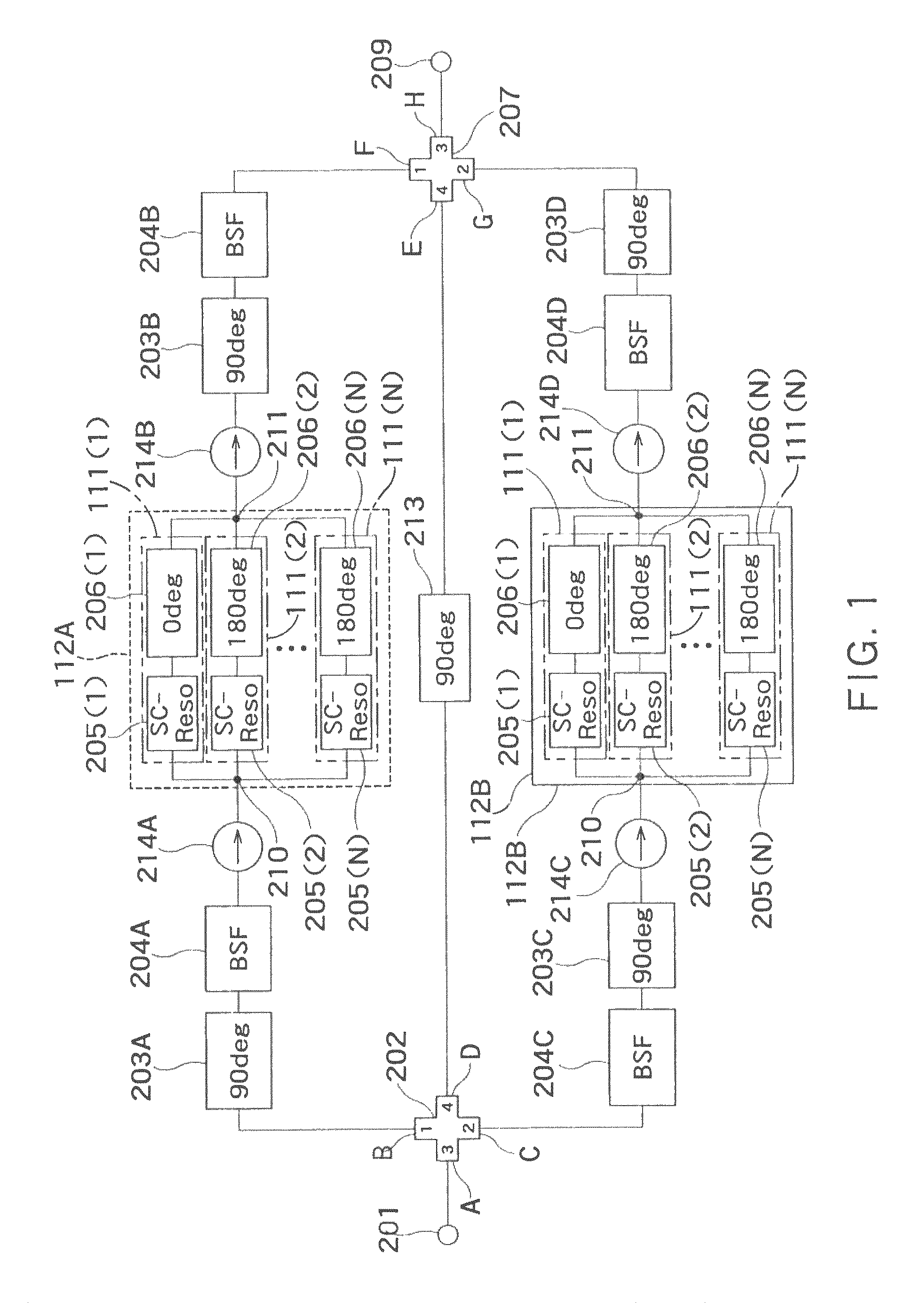
[0067]FIG. 1 shows a filter circuit according to the present invention.

[0068]A filter circuit of the present embodiment divides a signal, which has a certain band and was inputted into an input terminal 201, with the use of a band stop filter into a signal (with a large power density) in a stop band and a signal (with a small power density) in a pass band outside the stop band, extracts a signal in a desired band from the signals in the pass band with the use of a resonator circuit including a plurality of superconductive resonators, and combines the extracted signal in the desired band with the signal in the stop band, to output the signal from an output terminal 209.

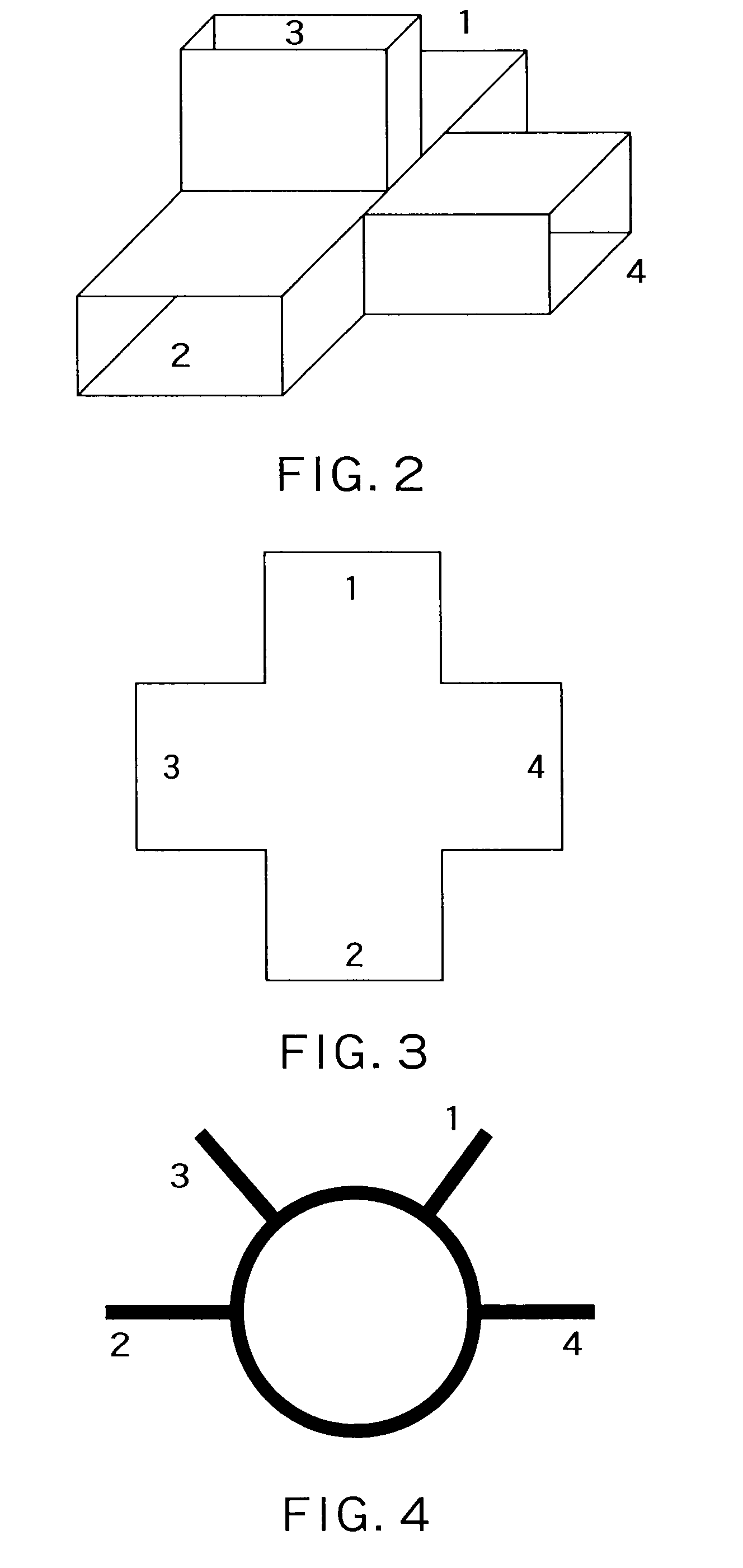
[0069]In the present filter circuit, four-port elements 202 and 207 having an S parameter defined in the following formula are used. Respective terminals of the four-port elements 202 and 207 are defined as terminals 1, 2, 3, and to 4.

[0070][S]=12⁡[001100-111-1001100]

[0071]Examples of the four-port element may include ...

second embodiment

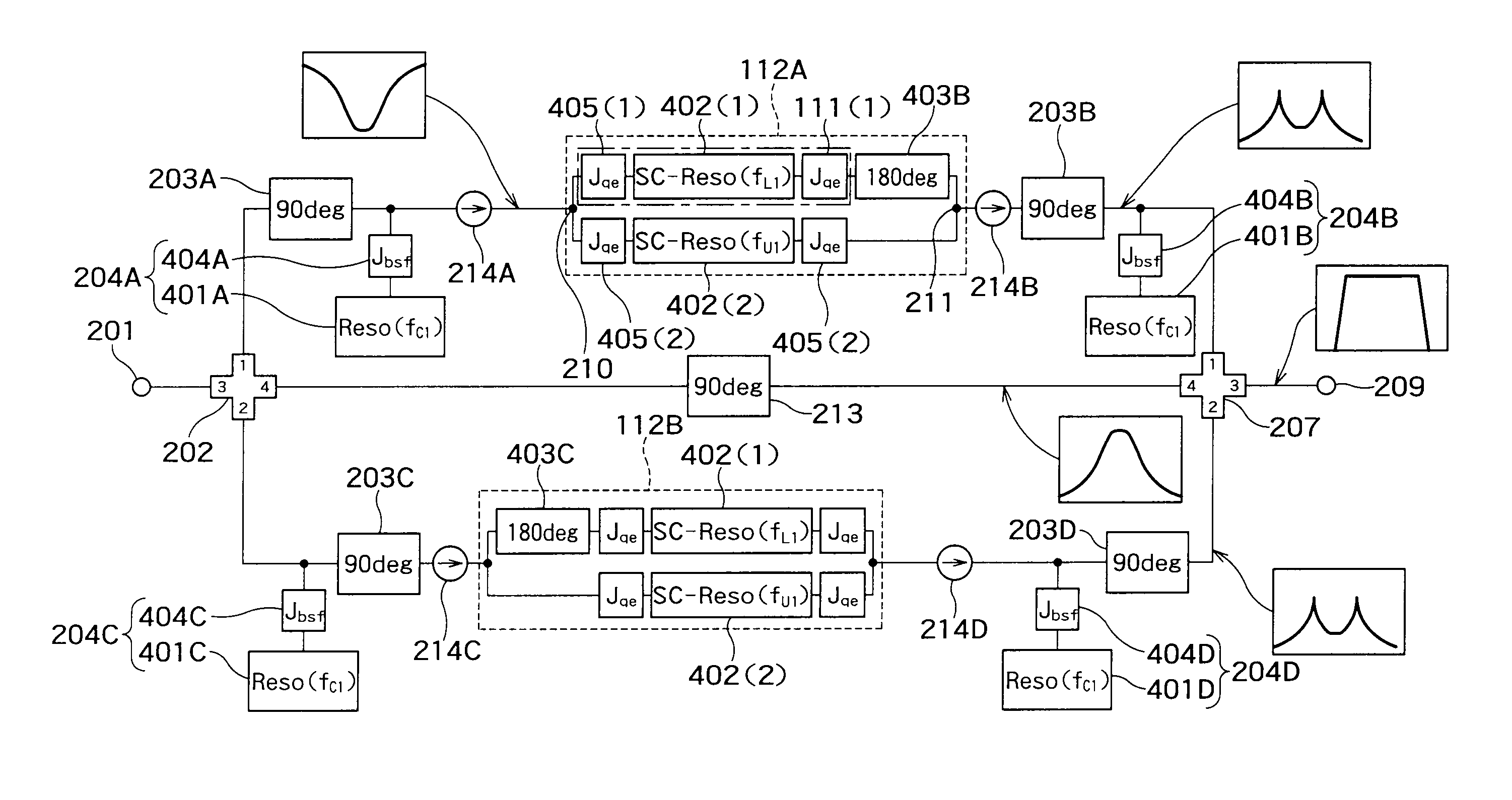
[0111]FIG. 16 shows the filter circuit according to the present invention.

[0112]This filter circuit differs chiefly from the filter circuit in FIG. 1 in configuration of the resonator circuits 112A and 112B. In the resonator circuits 112A and 112B in this filter circuit, a plurality of blocks 111(N), where two superconductive resonators 402(N) sandwiched by three coupling circuits and delay circuits (403A and 403B) are cascade-connected, are connected in parallel between the power divider 210 and the power combining unit 211. In addition, in the resonator circuit 112B, the delay circuits 403A and 403B are placed not immediately before the power combining unit 211, but immediately after the power divider 210. However, those circuits may be arranged immediately before the power combining unit 211.

[0113]The power handling capability Wreso of the resonator 402(N) inside each of the resonator circuits is smaller than the power handling capability Wbsf of each of the band stop filters 204...


PUM

PropertyMeasurementUnit
resonance frequencyaaaaaaaaaa
transmissionaaaaaaaaaa
inductanceaaaaaaaaaa

Abstract

There is provided a signal processing method comprising: inputting an input signal having a certain band; dividing said input signal into a signal in a stop band and a signal in a pass band outside said stop band with a use of a band stop filter which has a center frequency of said input signal inside said stop band and includes a first resonator having said center frequency as a resonance frequency; extracting a signal in a desired band from the signal in said pass band with a use of a plurality of second resonators; decomposing the signal in said stop band into signals whose degeneracy of said resonance frequency are released; combining a degeneracy-released signals and the signal in said desired band to obtain a combined signal; and outputting the combined signal.

Description

CROSS REFERENCE TO RELATED APPLICATIONS[0001]This application is based upon and claims the benefit of priority from the prior Japanese Patent Applications No. 2007-220913, filed on Aug. 28, 2007; the entire contents of which are incorporated herein by reference.BACKGROUND OF THE INVENTION[0002]1. Field of the Invention[0003]The present invention relates to a filter circuit, radio communication equipment and a signal processing method, and for example relates to a filter circuit for band limitation which is connected to a post stage of a power amplifier for use in a transmission unit of communication equipment using radio.[0004]2. Related Art[0005]Conventionally, as shown in FIG. 23, a filter circuit is configured by cascade-connecting resonators 1107(1), 1107(a), 1107(3), . . . 1107(n). An equivalent circuit of each resonator is made up of an inductor and a capacitor, and is also added with a resistor in the case of considering an effect of a loss. A resonance frequency in the case ...

Claims


Application Information

Patent Timeline
Patent Type & Authority Patents(United States)
IPC IPC(8): H01P1/20H01B12/02
CPCH01P1/20H04B1/52
Inventor KAYANO, HIROYUKI
Owner KK TOSHIBA
Why Eureka
Try Eureka