Suspension trailing arm

a trailing arm and suspension technology, applied in the direction of resilient suspensions, vehicle springs, interconnection systems, etc., can solve the problems of inefficient suspension packaging (i.e., space requirements), restricted trailing arm shape, and inability to meet the needs of additional components, so as to reduce the weight of the trailing arm and reinforce the potential failure poin

Inactive Publication Date: 2011-05-24
MERITOR HEAVY VEHICLE SYST
View PDF14 Cites 8 Cited by
  • Summary
  • Abstract
  • Description
  • Claims
  • Application Information

AI Technical Summary

Benefits of technology

[0013]Preferably, this reduces the weight of the trailing arm, which may provide additional benefits for the fuel consumption or load capacity of a vehicle to which the trailing arm is fitted.
[0014]Furthermore, composite manufacturing techniques allow the shape of the trailing arm to be tailored to meet the packaging requirements of the additional components mounted to and around the trailing arm. The same manufacturing techniques also allow the properties of the trailing arm to be locally tailored by varying the composition of the composite material used. Therefore, for example, a known potential failure point can be reinforced by using a composite material of appropriate composition. Additionally, composites do not suffer from the same corrosion problems associated with steel components.

Problems solved by technology

One disadvantage of known manufacturing techniques is that the shape of the trailing arm is restricted, which in turn restricts the positioning of additional components that are mounted to the trailing arms, such as brakes, air springs, dampers and pivot bushings.
This may cause the suspension packaging (i.e., its space requirement) to be inefficient.
Another disadvantage of known trailing arms is that it is timely to secure the trailing arm to the axle, for example, by fastening or welding.

Method used


Image

  • Suspension trailing arm
  • Suspension trailing arm
  • Suspension trailing arm

Examples


Embodiment Construction

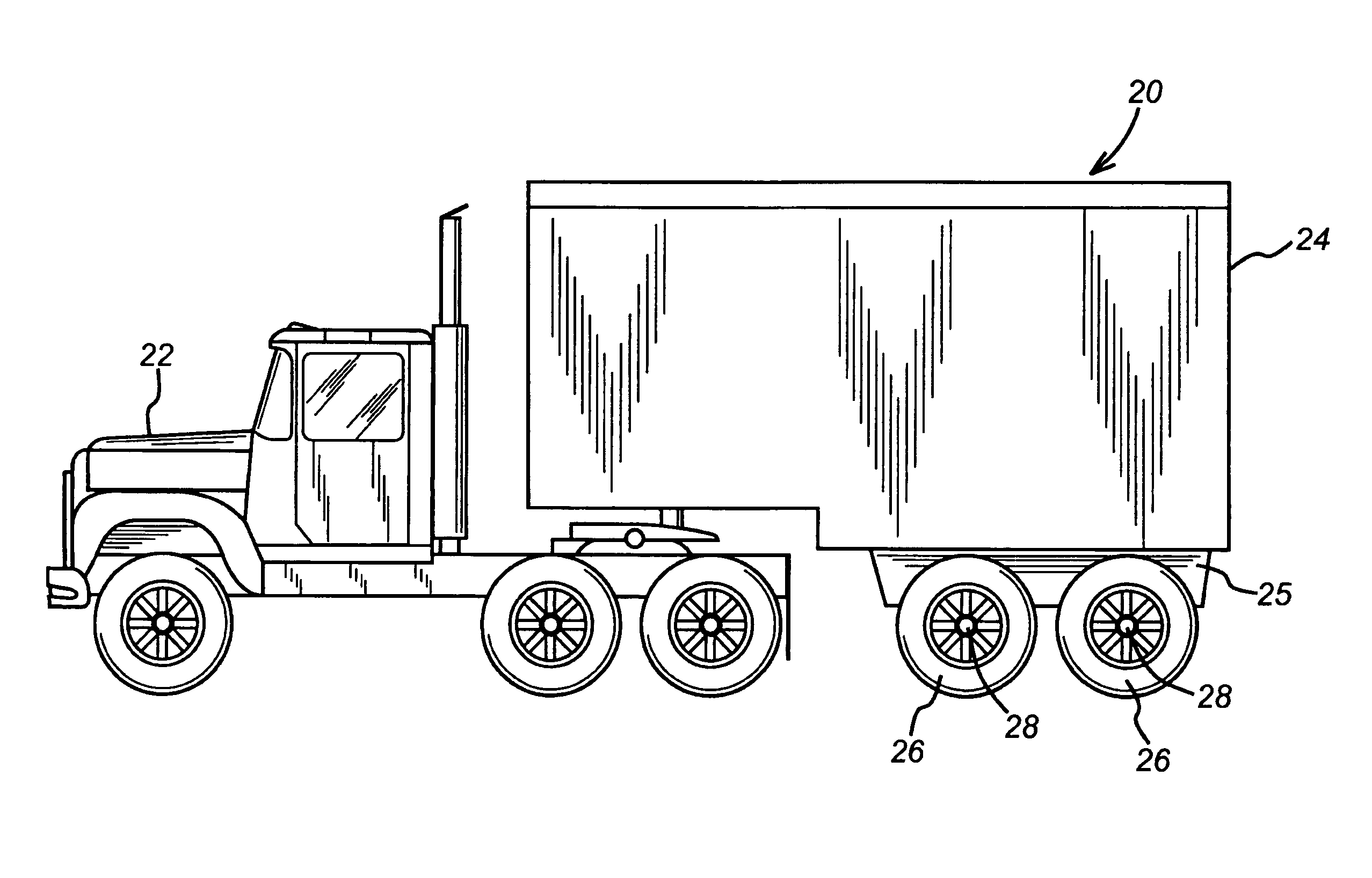
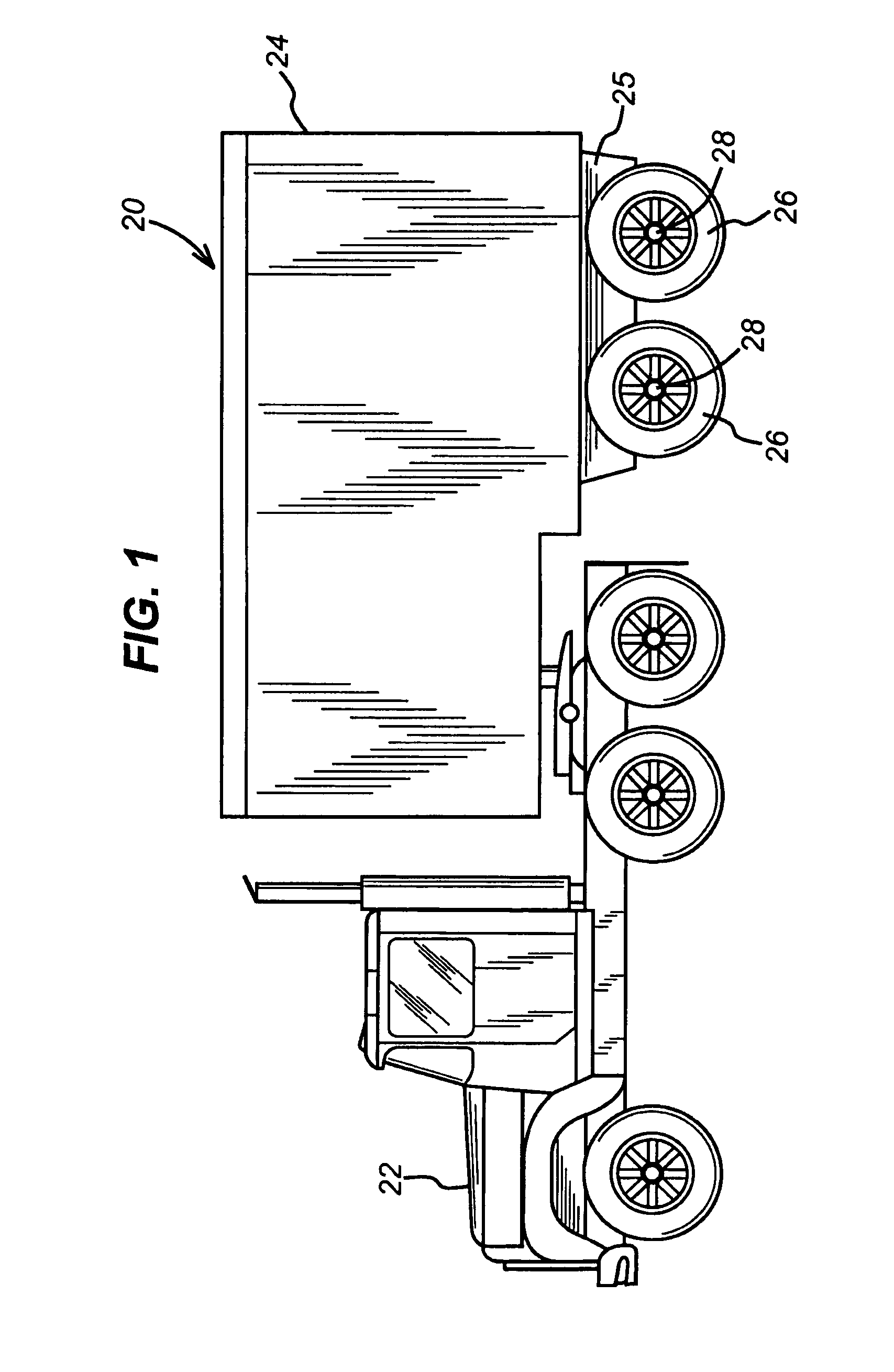
[0024]FIG. 1 illustrates a heavy commercial vehicle 20 including a tractor portion 22 and a trailer portion 24 mounted for articulation relative to the tractor portion 22. A plurality of wheels 26 are suspended from a chassis 25 of the trailer portion 24 and each rotate about an axis 28.

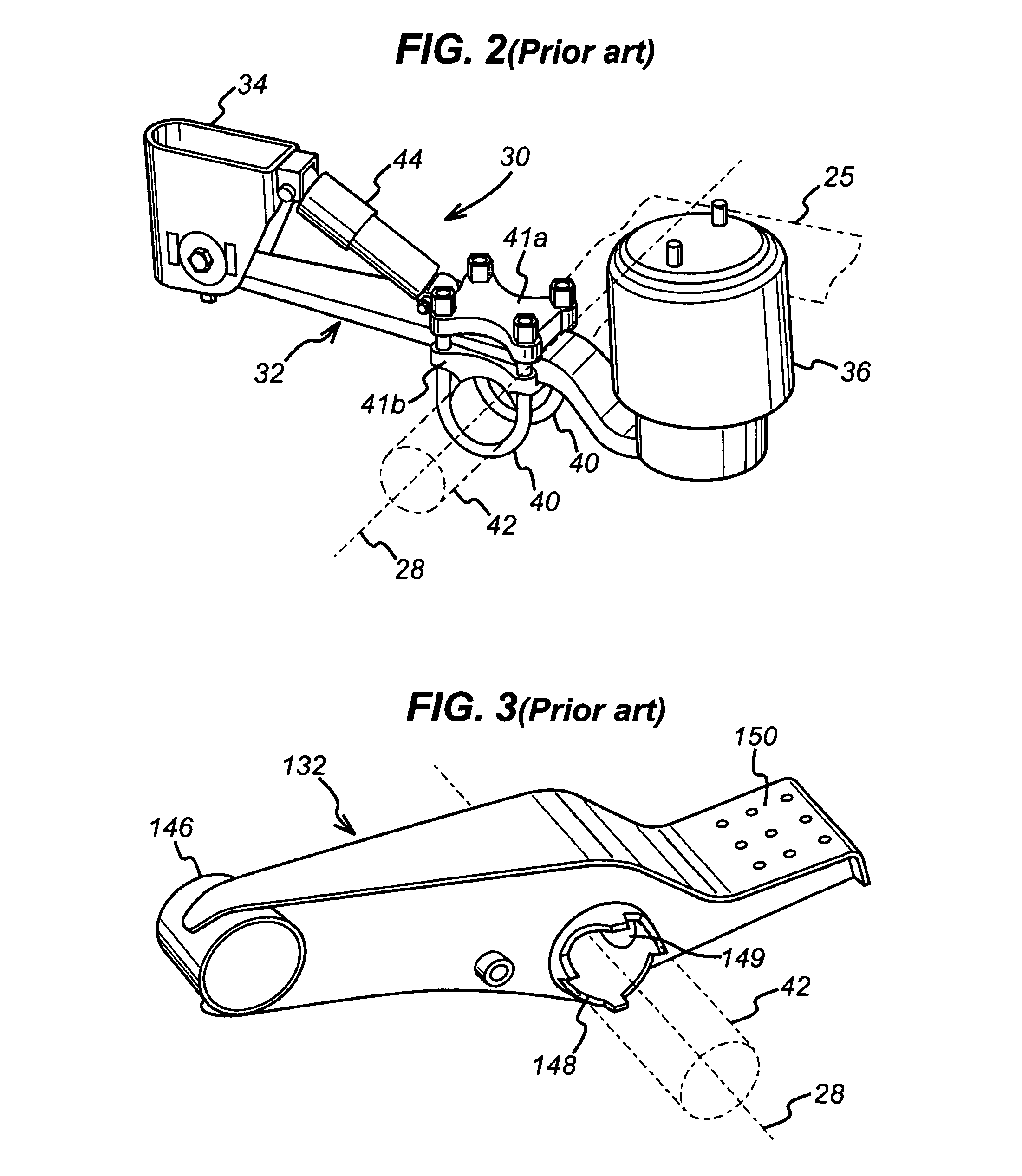
[0025]FIG. 2 shows a prior art suspension assembly 30 which includes a spring steel suspension trailing arm 32, a chassis support bracket 34 and an air spring 36. The chassis support bracket 34 and the air spring 36 provide a connection with, and suspension relative to, a trailer chassis 25 (shown in broken lines for clarity) in a known manner. U-bolts 40 and top and bottom plates 41a and 41b, respectively, mount an axle 42 (shown in broken lines for clarity) to the trailing arm 32. In particular, the bottom plate 41b is welded directly to axle 42. Wheels (not shown) are secured to each end of the axle 42 and rotate about the axis 28. A damper 44 mounted between the chassis support bracket 34 and the...


PUM


Abstract

A composite suspension trailing arm for heavy commercial vehicles includes an axle locating portion integral with the trailing arm, a chassis mounting feature to mount the trailing arm to a chassis component of a vehicle and a spring mounting feature integral with the trailing arm. The axle locating portion is located between the chassis mounting feature and the spring mounting feature. The composite material is made of a matrix material and a reinforcement material.

Description

REFERENCE TO RELATED APPLICATION[0001]This application claims priority to Great Britain Patent Application GB 0313804.7 filed on Jun. 14, 2003.BACKGROUND OF THE INVENTION[0002]The present invention relates to a suspension trailing arm, and in particular to a composite suspension trailing arm for a heavy commercial vehicle.[0003]Heavy commercial vehicles typically employ trailing arm suspension systems, particularly in relation to the rear axles of rigid body vehicles or the axles of trailers of articulated vehicles.[0004]Heavy commercial vehicles (including trucks, buses and coaches) can be distinguished from light commercial vehicles (such as vans) and light passenger vehicles due to one or more of the following characteristics: 1) a laden weight in excess of approximately 3.5 tons, and 2) the use air actuated brakes as opposed to hydraulically actuated brakes (because air actuated brakes are better able to withstand the increased heat generated by the repeated braking of a vehicle...

Claims


Application Information

Patent Timeline
Patent Type & Authority Patents(United States)
IPC IPC(8): B60G3/12B60G9/00
CPCB60G9/003B60G2200/31B60G2202/152B60G2300/02B60G2204/4306B60G2206/7101B60G2204/148
Inventor HUGHES, THOMAS
Owner MERITOR HEAVY VEHICLE SYST
Why Eureka
Try Eureka