Large airborne time-domain electromagnetic transmitter coil system and apparatus

a technology of electromagnetic transmitter coil and large airborne time domain, which is applied in the field of airborne geological mapping, can solve the problems of limiting the amount of current in the transmitter coil by electrical resistance, reducing aerodynamics and increasing drag, and limiting the size of rigid structures that can be deployed without breaking

Active Publication Date: 2011-05-24
GEOTECH
View PDF7 Cites 40 Cited by
  • Summary
  • Abstract
  • Description
  • Claims
  • Application Information

AI Technical Summary

Benefits of technology

In this respect, before explaining at least one embodiment of the invention in detail, it is to be understood that the invention is not limited in its application to the details of construction and to the arrangements of the components set forth in the following description or illustrated in the drawings. The invention is capable of other embodiments and of being practiced and carried out in various ways. Also, it is to be understood that the phraseology and terminology employed herein are for the purpose of description and should not be regarded as limiting.

Problems solved by technology

In this case, the limiting factor for the amount of current in the transmitter coil is the electrical resistance of the coil and tow cable.
However, increasing the transmitter coil diameter may reduce aerodynamics and increase drag.
Large structures may be stressed during take-off and landing, and therefore there is generally a limit for the size of rigid structures that can be deployed without breaking apart.
Reinforcing the structure so that it does not break during take-off and landings may mean an increase in the weight of the structure.
An overall flexible frame can be difficult to utilize in rugged terrain where it can be broken or damaged during take-off or landing upon uneven ground.
None of the above-referenced systems are able to address the interest in exploring base metals and uranium deposits at depths approaching 1 kilometer.
A limitation of the known HTEM systems is that there is no transmitter coil available that simultaneously: offers a large magnetic dipole moment; attains good flight stability; that is light weight; that is compatible with small aircraft, in particular small single-engine helicopters; and is easy to transport, setup and repair in the field.

Method used


Image

  • Large airborne time-domain electromagnetic transmitter coil system and apparatus
  • Large airborne time-domain electromagnetic transmitter coil system and apparatus
  • Large airborne time-domain electromagnetic transmitter coil system and apparatus

Examples


Embodiment Construction

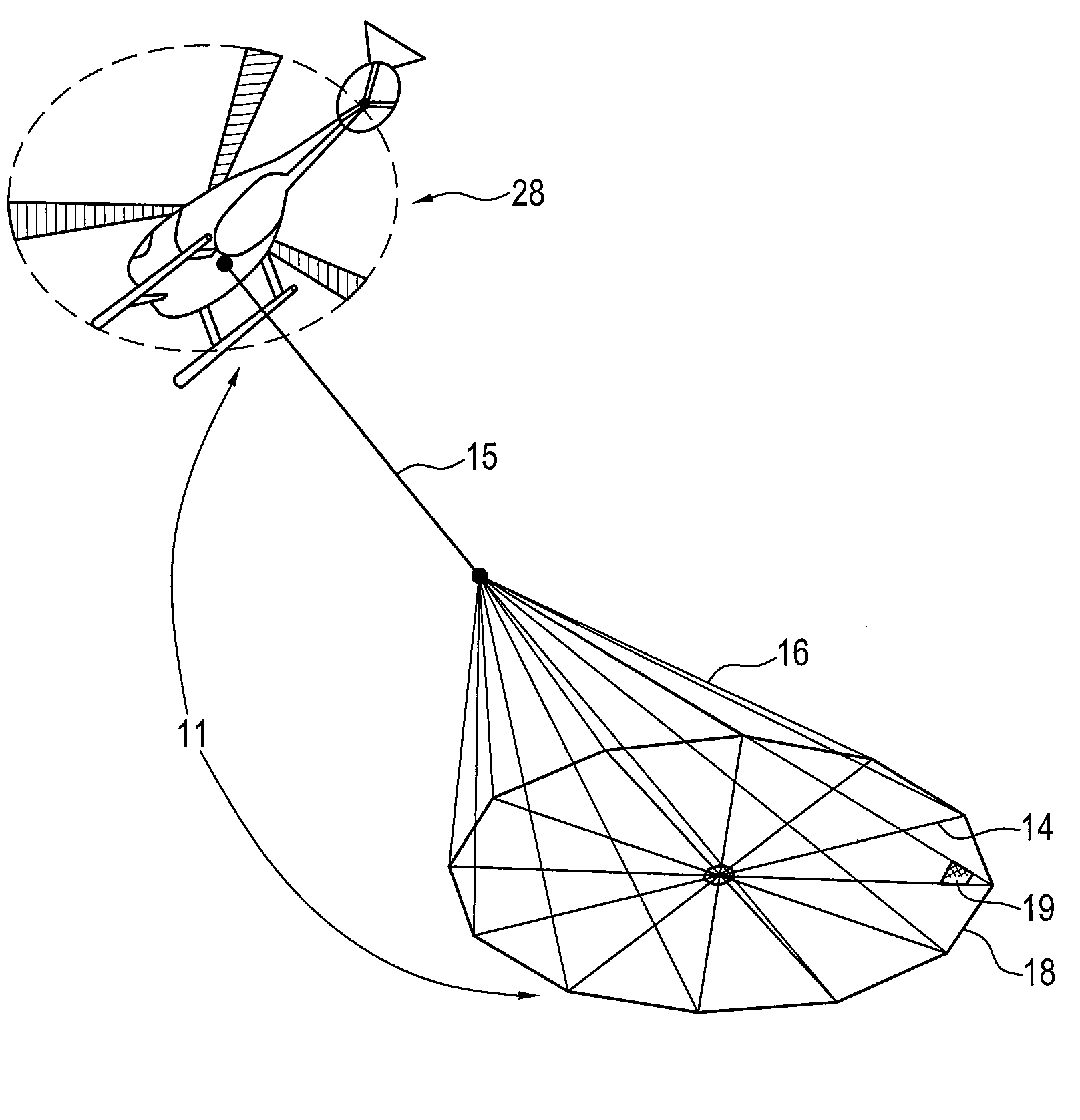
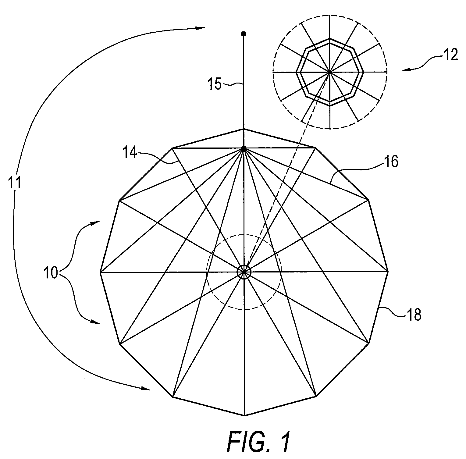
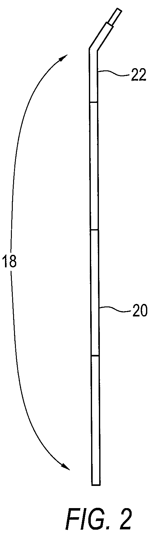
The present invention consists of a large transmitter coil which can be deployed by an aircraft, such as a single-engine helicopter, and which may be used in a time-domain electromagnetic system such as an airborne HTEM survey system. There is a need for a transmitter coil in the field of electromagnetic surveying systems having particular features such as size scalability, and a structure that is repairable in the field. The structure of the transmitter of the present invention may be a semi-rigid structure that reduces the likelihood of breakage when it is flown from an aircraft, such as a low-cost small-engine helicopter. Moreover, it may be formed of sections whereby it can be repaired in the field and allow for scalable size of the structure.

Thus, the system and apparatus of the present invention may address the interest in exploring base metals and uranium deposits at depths of a certain distance for example those in the range of I kilometer. It can encompass a transmitter ass...


PUM


Abstract

An airborne time domain electromagnetic survey system is provided. The system and apparatus of the present invention are able to address the interest in exploring base metals and uranium deposits at depths approaching 1 kilometer. It encompasses a transmitter coil having a large magnetic dipole moment, flight stability, which is light weight, compatible with small helicopters, and can be transported, setup and repaired in the field. It is of a semi-rigid modular structure that can decrease the incidence of damage or breakage during take-off or landing in rough terrain.

Description

FIELD OF INVENTIONThis invention relates in general to the field of airborne geological mapping. This invention further relates to a system and apparatus for conducting helicopter-mounted time-domain electromagnetic surveys.BACKGROUND OF THE INVENTIONThere are a variety of known electromagnetic techniques. Geophysical electromagnetic (“EM”) techniques can be effective in determining the electrical conductivity of soils, rocks and other conductive material at depths up to about one kilometer. Conductivity distribution with depth is of great interest in mapping base metals and uranium deposits, aquifers and other geological formations. Geophysical EM methods generally involve generation of a magnetic field by applying a periodic current to a transmitter coil system placed near the earth's surface. This primary magnetic field induces electrical currents in the ground, and the secondary magnetic field produced by these currents is measured to provide information about ground conductivit...

Claims


Application Information

Patent Timeline
Patent Type & Authority Patents(United States)
IPC IPC(8): G01V3/16
CPCG01V3/17G01V3/165G01V3/16
Inventor KUZMIN, PETR VALENTINOVICHMORRISON, EDWARD BEVERLY
Owner GEOTECH
Why Eureka
Try Eureka