
Electromotive rectification system

a rectification system and electromotive technology, applied in the field of electric systems, can solve the problems of short transient variations in return current on the neutral conductor, and less efficient electrical power usag

Active Publication Date: 2011-05-24
CUTT A WATT ENTERPRISES
View PDF6 Cites 19 Cited by
  • Summary
  • Abstract
  • Description
  • Claims
  • Application Information

AI Technical Summary

Benefits of technology

"The present invention solves the problems of previous AC neutral bus electromotive power rectification units by providing a first and second coil unit. The first coil unit includes a conductive wire coil suspended in a non-conductive tube, while the second coil unit includes a conductive wire coil surrounded by a non-conductive material. The first coil unit is connected to the neutral bus bar at a first position, while the second coil unit is connected to the outside neutral wire at a second position. The invention is useful in an electrical power distribution box with a neutral bus bar and multiple inside and outside neutral wires. The technical effects of the invention include improved efficiency, reduced size, and improved reliability of the AC neutral bus electromotive power rectification unit."

Problems solved by technology

Due to mechanical inefficiencies in many household appliances and in industrial machinery, short transient variations in return current can be experienced on the neutral conductor.
These transients can make electrical power usage less efficient.

Method used


Image

  • Electromotive rectification system
  • Electromotive rectification system
  • Electromotive rectification system

Examples


Embodiment Construction

[0017]A preferred embodiment of the invention is now described in detail. Referring to the drawings, like numbers indicate like parts throughout the views. Unless otherwise specifically indicated in the disclosure that follows, the drawings are not necessarily drawn to scale. As used in the description herein and throughout the claims, the following terms take the meanings explicitly associated herein, unless the context clearly dictates otherwise: the meaning of “an,” and “the” includes plural reference, the meaning of “in” includes “in” and “on.”

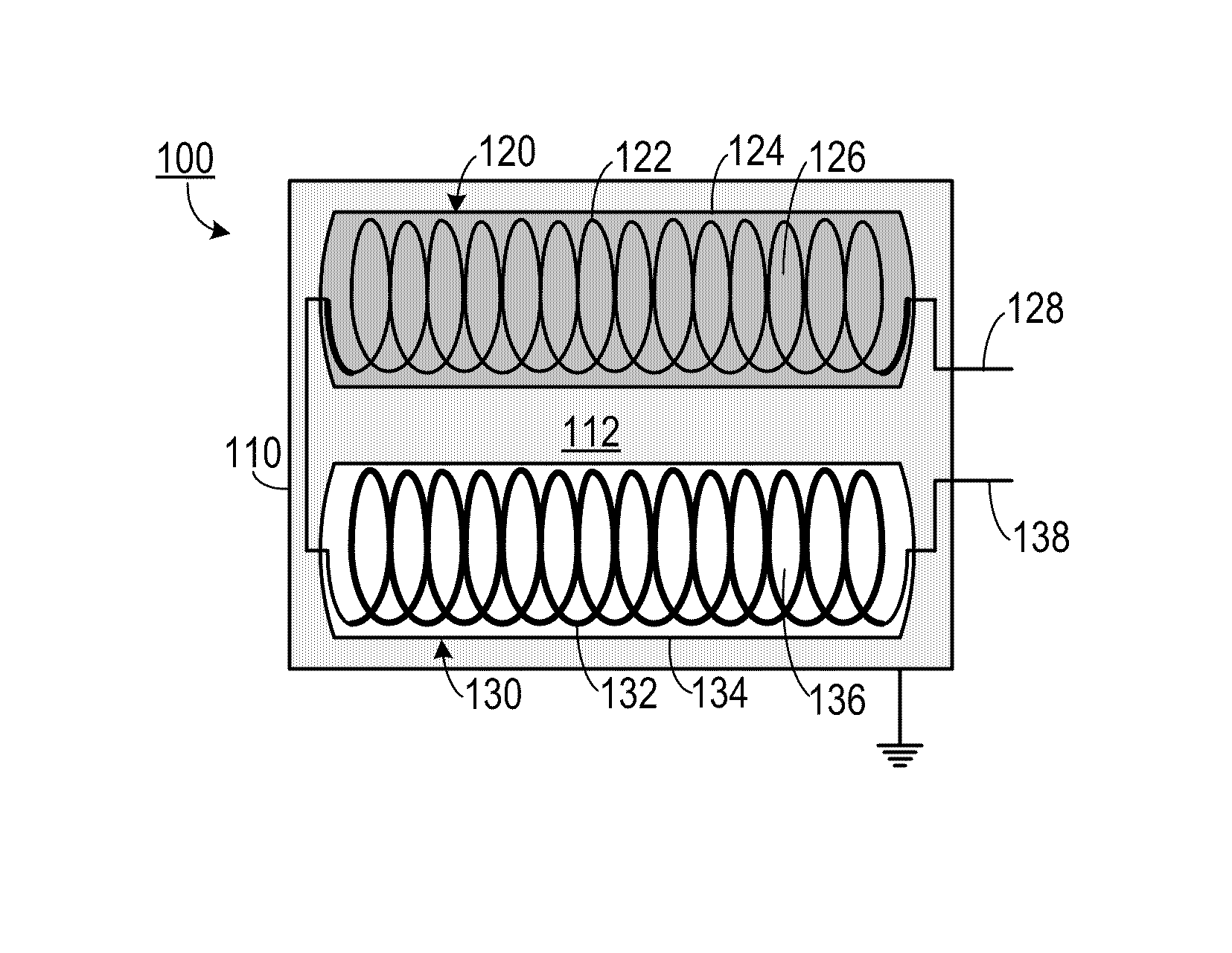
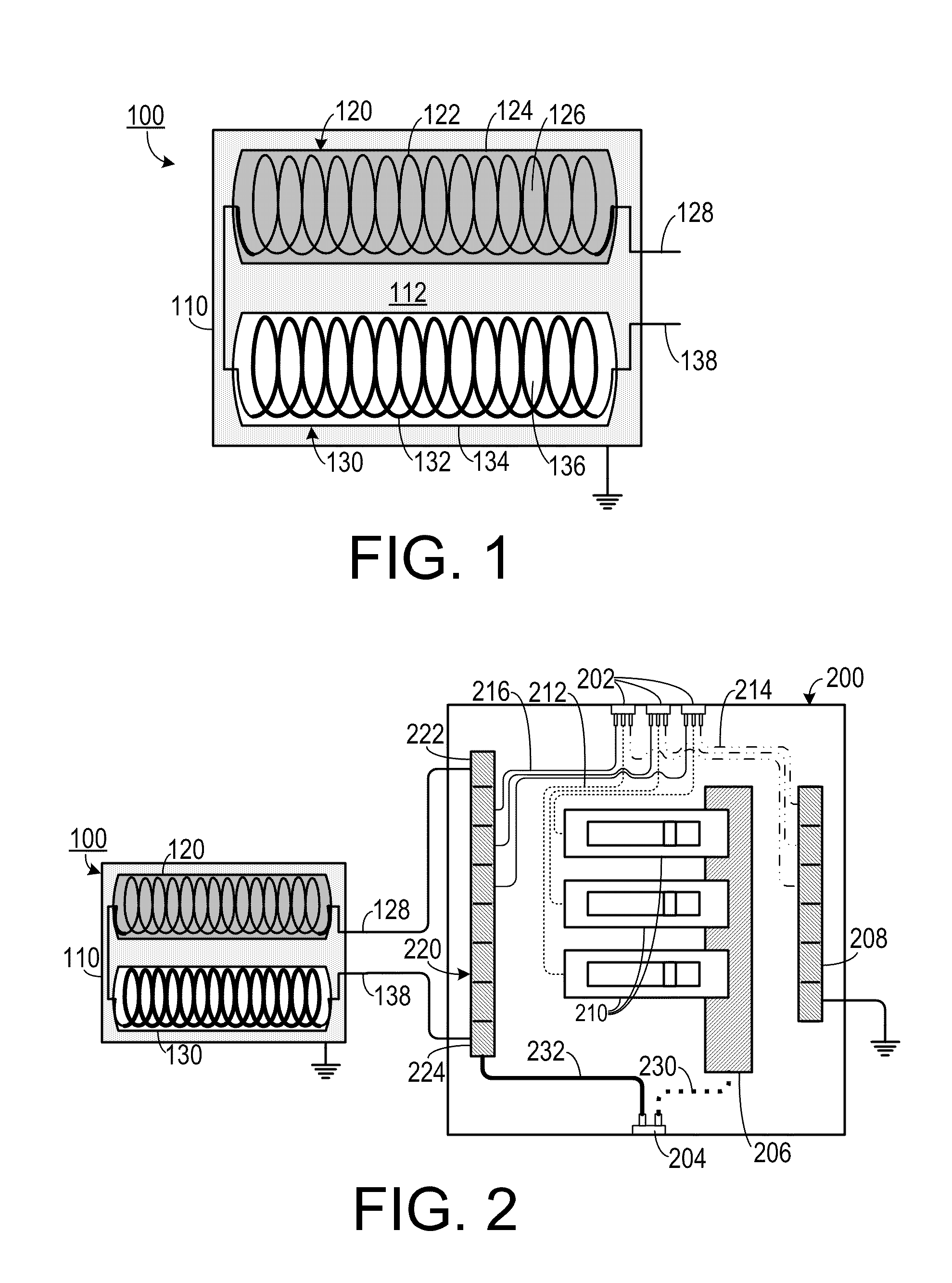
[0018]As shown in FIG. 1, one representative embodiment of a electromotive rectification system 100 includes a housing 110, preferably made of a conductive material such as a metal that is grounded, in which is disposed a first coil unit 120 and a spaced-apart second coil unit 130. In an alternate embodiment, the housing 110 could include a non-conductive material, such as a plastic or fiberglass.

[0019]The first coil unit 120 includes a no...


PUM

PropertyMeasurementUnit
conductiveaaaaaaaaaa
non-conductiveaaaaaaaaaa
electrical currentaaaaaaaaaa

Abstract

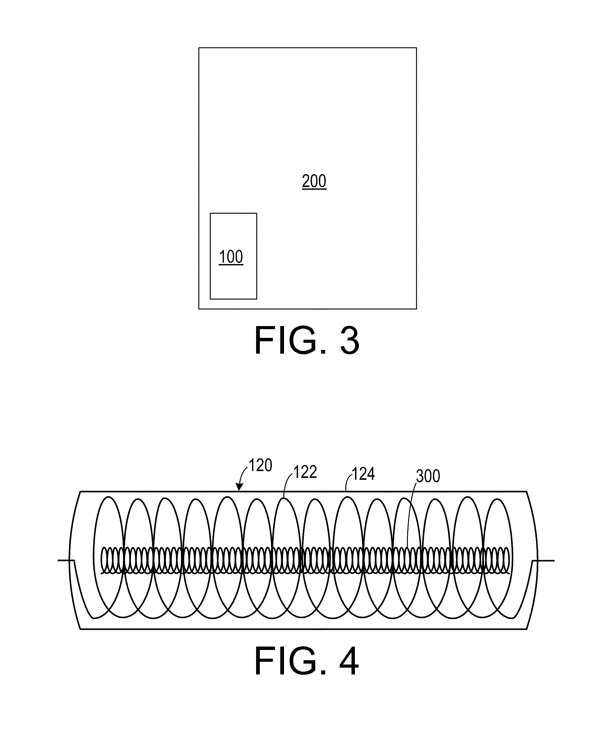
An AC neutral bus electromotive power rectification unit includes a first coil unit and a second coil unit. The first coil unit includes a first conductive wire coil having a first end and an opposite second end. The conductive coil is disposed in a first non-conductive tube and is suspended in a ferrous matrix. The second coil unit includes a second conductive wire coil having a first end and an opposite second end. The first end of the second coil unit is electrically coupled to the first end of the first coil unit. The second coil unit is disposed in a second non-conductive tube and is surrounded by a non-conductive material.

Description

CROSS-REFERENCE TO RELATED APPLICATION[0001]This application claims the benefit of U.S. Provisional Patent Application Ser. No. 61 / 083,402, filed Jul. 24, 2008, the entirety of which is hereby incorporated herein by reference.BACKGROUND OF THE INVENTION[0002]1. Field of the Invention[0003]The present invention relates to electrical systems and, more specifically, to an electrical system used in cooperation with an electrical power distribution system.[0004]2. Description of the Prior Art[0005]Electrical power systems typically employ a “hot” electrical conductor that delivers current to a location and a “neutral” conductor that allows return of electrical current to its source. Due to mechanical inefficiencies in many household appliances and in industrial machinery, short transient variations in return current can be experienced on the neutral conductor. These transients can make electrical power usage less efficient.[0006]Therefore, there is a need for a system that minimizes the ...

Claims


Application Information

Patent Timeline
Patent Type & Authority Patents(United States)
IPC IPC(8): H01F27/02H01F21/02H01F27/28
CPCH01F37/00H01F17/045
Inventor LONG, JOHN M.
Owner CUTT A WATT ENTERPRISES
Learn More