Method of making a deposit on an SiC-covered substrate

a technology of sic and deposit, applied in the direction of mechanical means, electrical/magnetic measuring arrangements, machines/engines, etc., can solve the problems of failure mode rupture at the interface between, damage to the sic surface without creating favorable roughness, etc., to improve mechanical anchoring of the coating on the sic, improve physicochemical bonding, and increase the roughness of the surface

Active Publication Date: 2011-05-31
SN DETUDE & DE CONSTR DE MOTEURS DAVIATION S N E C M A
View PDF7 Cites 0 Cited by
  • Summary
  • Abstract
  • Description
  • Claims
  • Application Information

AI Technical Summary

Benefits of technology

[0007]The invention seeks to provide a method of making a coating on a part with a surface of silicon carbide (SiC) and that enables the tenacity of the interface between the SiC surface and the coating to be improved.
[0009]a) applying laser treatment to the SiC surface by superposing laser impacts for the purpose of increasing the roughness of said surface; and
[0011]By means of the repeated impacts of the laser beam on the SiC surface, the roughness of this surface is increased, thereby enhancing the mechanical anchoring of the coating on the SiC surface. In addition, the laser beam modifies the physicochemical state of the SiC surface, thereby enhancing physicochemical bonding between the coating and the SiC surface. Thus, the interface between the part and the coating is better at withstanding high temperatures.
[0017]a) applying laser treatment to the SiC layer by superposing laser impacts for the purpose of increasing the roughness of said layer;
[0025]Because of the repeated impacts of the laser beam on the surface of the SiC layer, the roughness of said surface increases, thereby enhancing mechanical anchoring of the coating on the SiC layer. In addition, the laser modifies the physicochemical state of the surface of the SiC layer, thus improving physicochemical bonding between the coating and the SiC layer.
[0026]Thus, the interface between the part and the coating is better at withstanding high temperatures, and the strain gauge remains secured to the SiC layer and thus to the part whose deformation is to be measured at high temperatures. Consequently, it is possible to take more accurate measurements of the deformation of the part on which the gauge is fastened.

Problems solved by technology

Mechanical and thermal testing carried out on parts having SiC surfaces covered in a ceramic coating show that the main failure mode is rupture at the interface between the SiC surface and the ceramic coating, probably because of the physicochemical properties of the SiC surface.
Nevertheless, sand blasting leads to damage to the SiC surface without creating favorable roughness.

Method used


Image

  • Method of making a deposit on an SiC-covered substrate
  • Method of making a deposit on an SiC-covered substrate
  • Method of making a deposit on an SiC-covered substrate

Examples


Embodiment Construction

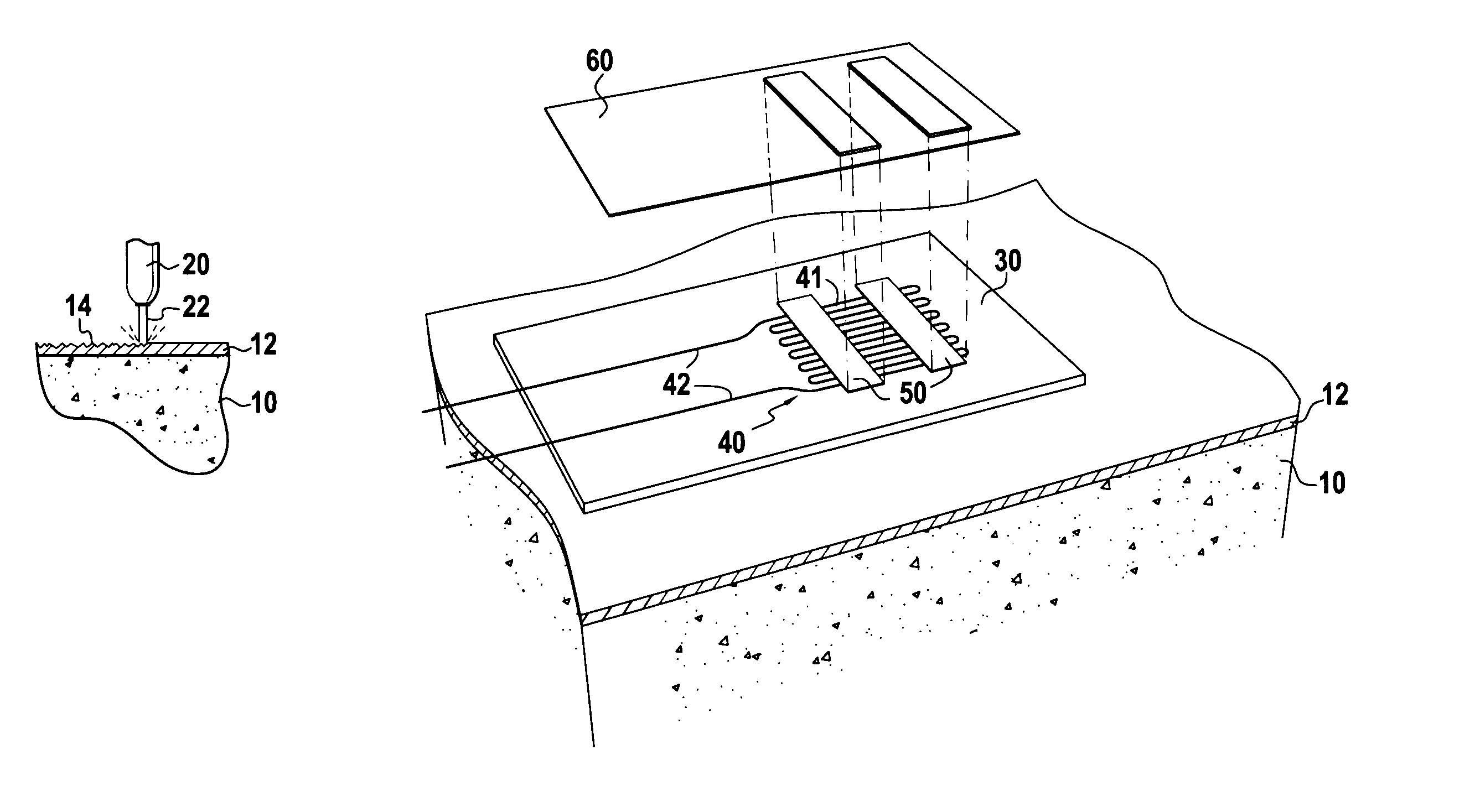
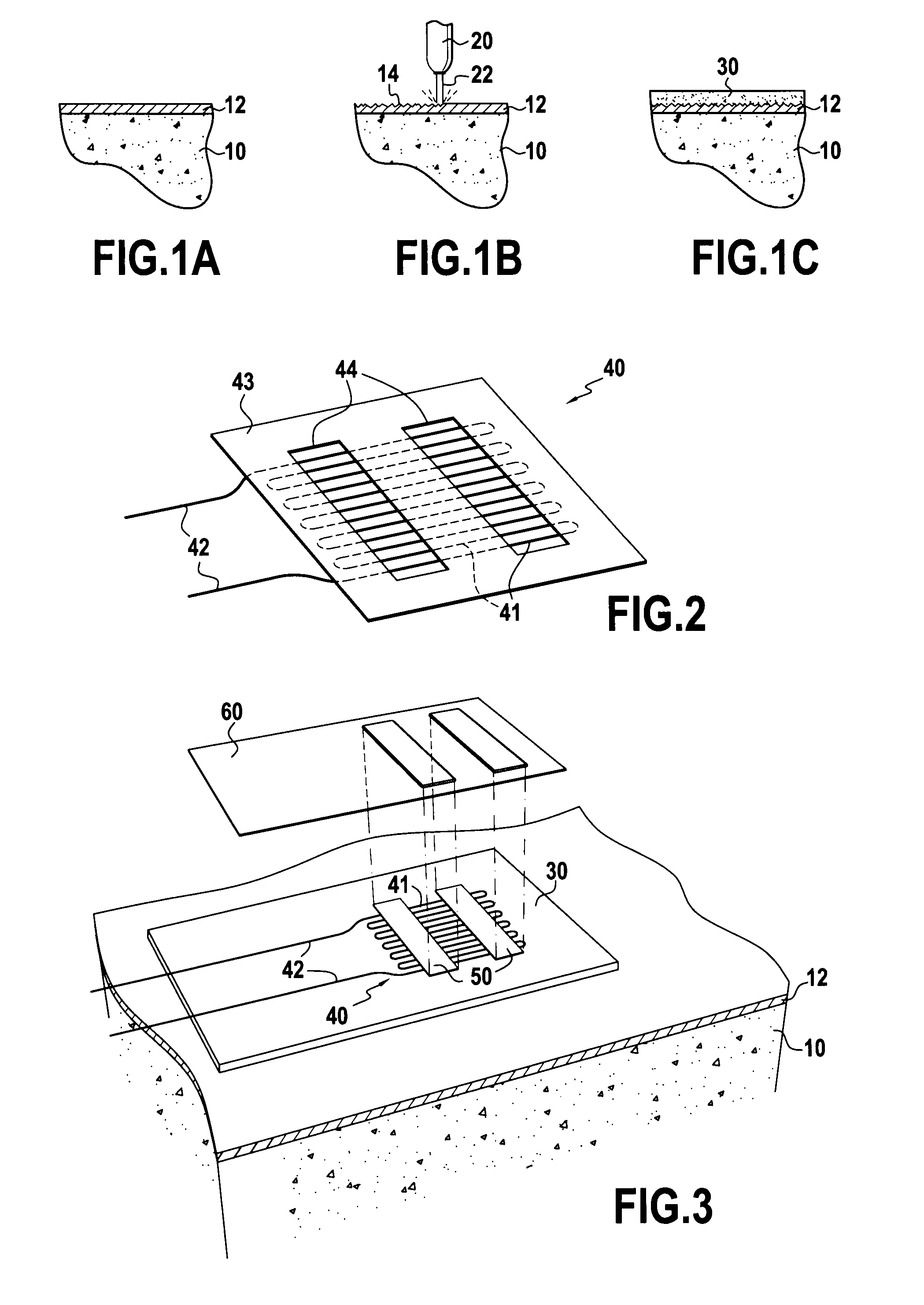
[0031]FIG. 1A shows a part for use in very high temperature applications, having a substrate 10 that is covered in a layer 12 of silicon carbide (SiC). By way of example, the substrate 10 is made of a ceramic matrix composite material, or of a self-healing ceramic matrix composite material. The composite material may be SiC or it may be formed by a plurality of refractory ceramic layers that are precursors of glass in the silicon boron carbon (Si—B—C) ternary system. Such composites are reinforced, for example, by fibers made of carbon or ceramic. In applications to aviation turbomachines, such parts are typically thin parts, of frustoconical or plane rectangular shape, and they present a size of the order of a few hundreds of millimeters.

[0032]The SiC layer 12 deposited on the substrate is deposited, for example, by the technique known as chemical vapor deposition.

[0033]FIG. 1B shows the same part, with a laser 20 emitting a laser beam towards the SiC layer 12. The laser beam impac...


PUM

PropertyMeasurementUnit
temperaturesaaaaaaaaaa
impact frequencyaaaaaaaaaa
sizeaaaaaaaaaa

Abstract

The invention relates to a method of depositing a coating on a part having its surface made of silicon carbide. The method comprises the following steps:a) applying laser treatment to the SiC surface by superposing laser impacts for the purpose of increasing the roughness of said surface; andb) depositing a coating on the SiC surface by atmospheric thermal spraying.The invention also provides a device for measuring deformation, which device comprises a first alumina coating obtained by atmospheric thermal spraying onto the silicon carbide layer covering the substrate of the part after it has been treated by superposing laser impacts, a free filament strain gauge placed on the coating, and an additional alumina coating obtained by atmospheric thermal spraying onto the strain gauge.

Description

[0001]The present invention relates to a method of depositing a coating on a part having its surface made of silicon carbide (SiC).BACKGROUND OF THE INVENTION[0002]The part may be a solid SiC part, or a part having a substrate that is not made of SiC and that is covered in an SiC layer. Parts comprising a substrate covered in an SiC layer are used in high temperature applications, i.e. applications for temperatures in the range 300° C. to 1100° C. By way of example, the substrate may be a ceramic matrix composite (CMC), i.e. a ceramic matrix reinforced by ceramic or carbon fibers, for example. The SiC layer is to give the part better resistance to oxidation and better mechanical properties at high temperatures. Because of these properties, such parts are used in particular in aviation turbomachines.[0003]In certain applications, it is necessary to deposit a coating on the SiC surface, e.g. a coating of metal or ceramic. In particular, it is possible to deposit a ceramic, such a cera...

Claims


Application Information

Patent Timeline
Patent Type & Authority Patents(United States)
IPC IPC(8): H01C17/28
CPCC04B41/009C04B41/52C04B41/87C04B41/89C23C4/005C23C4/02F01D21/003G01B7/18C04B41/4527C04B41/0036C04B41/5031C04B41/5037C04B41/5042C04B41/4531C04B41/5059C04B35/565C04B35/806Y10T29/49103C04B2111/00982Y10T29/49007C23C4/01
Inventor LEMAN, FREDERICLUKAT, SEBASTIENCOSTIL, SOPHIECODDET, CHRISTIAN
Owner SN DETUDE & DE CONSTR DE MOTEURS DAVIATION S N E C M A
Why Eureka
Try Eureka