Piston valve assembly of continuous damping control damper

a technology of damper and piston valve, which is applied in the direction of shock absorbers, vibration dampers, vibration suppression adjustments, etc., can solve the problems of unstable control of damper damping force, deterioration of coupling reliability, etc., and achieve stable control of damping force and coupling reliability between piston rod and piston valve assembly

Active Publication Date: 2011-05-31
S&T DAEWOO
View PDF15 Cites 11 Cited by
  • Summary
  • Abstract
  • Description
  • Claims
  • Application Information

AI Technical Summary

Benefits of technology

It is an object of the present invention to provide a piston valve assembly of a continuous damping control damper in which the reliability in coupling between the piston rod and the piston valve assembly is increased, thereby stably controlling the damping force of the damper.
It is an object of the present invention to provide a piston valve assembly having a damping property which is capable of improving the driving comports of a vehicle in the lower speed range.

Problems solved by technology

However, in the structure, since the tensile force of the piston rod 40, which is generated upon a tensile stroke, is concentrated on the key 37 and the groove portion 38 of upper plate 32, there is problem that the key 37 and the groove portion 38 are worn away each other while they are used for a long time, thereby deteriorating the reliability in coupling between them.
Furthermore, if there is formed a clearance between the key 37 and the groove portion 38 by the wear and tear, there is another problem that the controlling of the damping force of the damper 10 becomes unstable.

Method used


Image

  • Piston valve assembly of continuous damping control damper
  • Piston valve assembly of continuous damping control damper
  • Piston valve assembly of continuous damping control damper

Examples


Embodiment Construction

Reference will now be made in detail to the illustrated embodiment of the present invention, which is illustrated in the accompanying drawings.

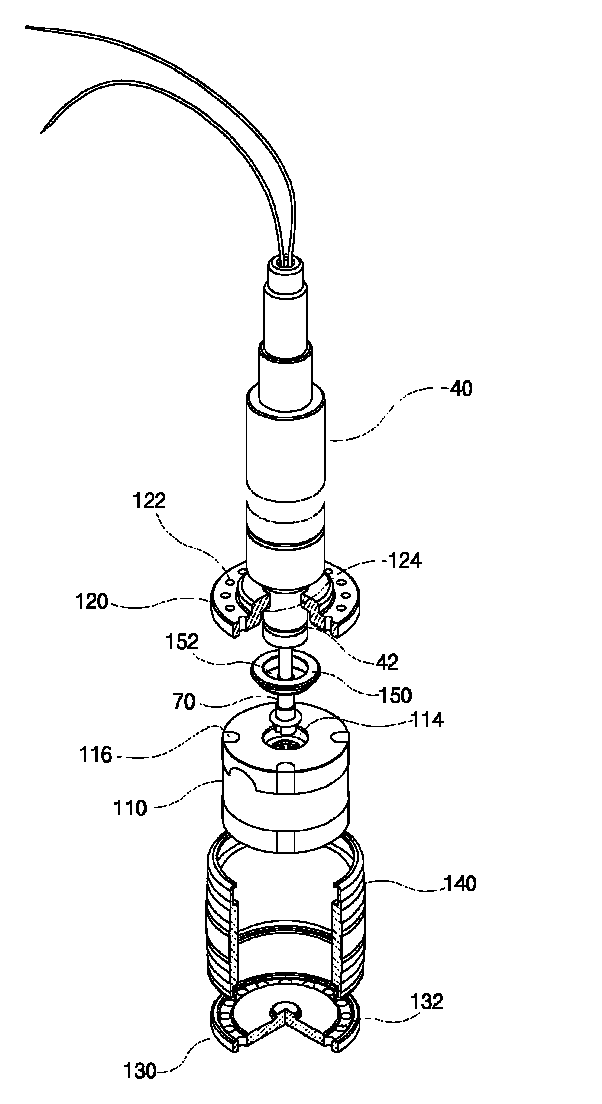
As shown in FIGS. 4 and 5, a piston valve assembly 100 according to the present invention includes a core assembly 110 which is fixed to a lower end of the piston rod 40 and provided with a solenoid coil, an upper plate 120 which is placed at an upper side of the core assembly 110, a lower plate 130 which is placed at a lower side of the core assembly 110, and a flux ring 140 which receives the core assembly 110, the upper plate 120 and the lower plate 130 therein.

On an upper surface of the core assembly 110, there is formed a rod coupling groove 114 in which the lower end of the piston rod 40 and a connecting cable 70 are inserted. The upper and lower plates 120 and 130 are respectively formed with a fluid passing hole 122, 132.

Particularly, the embodiment of the present invention is characterized by using a stopper 150 in order to more stab...


PUM


Abstract

The present invention relates to a piston valve assembly which is used in a continuous damping control damper using magneto-rheological fluid. The piston valve assembly is coupled with an end of the piston rod, and a stopper having a flat upper surface which is surface-contacted with an upper plate is disposed between a core assembly and the upper plate, thereby properly dispersing a force applied to the piston rod.According to the present invention, the reliability and stability in the coupling between the piston rod and the piston valve assembly can be increased, thereby stably controlling the damping force of the damper. Further, the slot is formed in the core of the piston valve assembly so as to reduce the damping force in the lower speed range, thereby considerably improving the driving comport of a vehicle.

Description

BACKGROUND OF THE INVENTIONThis application claims the benefit of Korean Patent Application No. 10-2007-0094296, filed on Sep. 17, 2007, in Korea, which is hereby incorporated by reference for all purposes as if fully set forth herein.FIELD OF THE INVENTIONThe present invention relates to a piston valve assembly and more particularly, to a piston valve assembly which is used in a continuous damping control damper using magneto-rheological fluid.DISCUSSION OF THE RELATED ARTIn general, a suspension is provided between a car body and a wheel so as to improve driving comports. The suspension includes a chassis spring for absorbing vibration and shock from a road surface, and a damper for damping free vibration of the chassis spring.The damper functions to absorb the free vibration of the chassis spring by converting vertical kinetic energy into heat energy, thereby rapidly damping the free vibration of the chassis spring.Recently, in a high-class motorcar, there is widely used an activ...

Claims


Application Information

Patent Timeline
Patent Type & Authority Patents(United States)
IPC IPC(8): F16F9/32F16F9/53
CPCF16F9/535F16F9/3228F16F9/32F16F9/34
Inventor JIN, MIN-HOLEE, DONG-RAKKANG, TAE-HO
Owner S&T DAEWOO
Why Eureka
Try Eureka