Method of controlling liquid droplet ejection apparatus, liquid droplet ejection apparatus, method of manufacturing electro-optical device, electro-optical device, and electronic device

a technology of liquid droplet ejection and liquid droplet, which is applied in the direction of printing, other printing apparatus, etc., can solve the problems of pressure variation (pulsation) and bad effect on print quality, and achieve the effect of not lowering the print quality

Inactive Publication Date: 2011-05-31
KATEEVA
View PDF20 Cites 7 Cited by
  • Summary
  • Abstract
  • Description
  • Claims
  • Application Information

AI Technical Summary

Benefits of technology

[0008]The invention has an advantage of providing a method of controlling a liquid droplet ejection apparatus in which the ink can be supplied under pressure without lowering the print quality, as well as providing an apparatus for ejecting liquid droplet, a method of manufacturing an electro-optical device, an electro-optical device and an electronic device.
[0011]In accordance with embodiments of the invention, in case the pressure inside the functional liquid tank is below the lower-limit pressure of the working pressure, confirmation is made to see whether the functional liquid droplet ejection head is in imaging operation or not. If it is not in the imaging operation, the functional liquid tank is pressurized to the upper-limit pressure of the working pressure so as to maintain the working pressure. Namely, since the supply under pressure of the functional liquid is performed while the functional liquid droplet ejection head is not in imaging operation, the supplying under pressure of the functional liquid does not influence the imaging result. It is therefore possible to perform highly accurate imaging with the functional liquid droplet ejection head.
[0014]In accordance with embodiments of the invention, in case the pressure inside the functional liquid tank is below the lower-limit pressure and also in case the functional liquid droplet ejection head is confirmed to be in the imaging operation, pressurizing is performed after confirming the position of the functional liquid droplet ejection head. Since the supplying under pressure of the functional liquid is performed when the functional liquid droplet ejection head is not in the imaging region, the effect of supplying under pressure of the functional liquid on the result of imaging on the imaging target can be kept as small as possible.
[0017]In accordance with embodiments of the invention, the upper-limit pressure in pressurization in case the functional liquid droplet ejection head is confirmed to be in imaging operation, is made to be that pressure during imaging operation which is lower than the upper-limit pressure. Therefore, the fluctuations of the in-head pressure (pressure in the passage inside the functional liquid droplet ejection head) before suspension of the imaging operation and after resumption thereof can be minimized. As a result, the supply under pressure of the functional liquid to be made during the suspension of the imaging operation can be effectively prevented from giving a bad effect on the result of imaging after the resumption of the imaging operation.
[0019]According to an embodiment of the invention, the functional liquid droplet ejection head during the supplying operation of the functional liquid under pressure can be caused to face the maintenance means to thereby perform maintenance operation on the functional liquid droplet ejection head during supplying of the functional liquid under pressure. It is thus possible to maintain in an appropriate condition the functional liquid droplet ejection head during supplying of the functional liquid under pressure.

Problems solved by technology

However, if the ink is supplied under pressure to the ink jet recording during printing, there will occur pressure variations (pulsations) in the in-head passage inside the ink jet recording head by the on-off operation of the pressurizing pump.
This may cause an unstable ejection of the ink droplets, resulting in a bad effect on the print quality.

Method used


Image

  • Method of controlling liquid droplet ejection apparatus, liquid droplet ejection apparatus, method of manufacturing electro-optical device, electro-optical device, and electronic device
  • Method of controlling liquid droplet ejection apparatus, liquid droplet ejection apparatus, method of manufacturing electro-optical device, electro-optical device, and electronic device
  • Method of controlling liquid droplet ejection apparatus, liquid droplet ejection apparatus, method of manufacturing electro-optical device, electro-optical device, and electronic device

Examples


first embodiment

[0056]The invention will be described with reference to the accompanying drawings. As the invention, a description will be made about an ink jet printer which is a kind of a liquid droplet ejection apparatus. This ink jet printer is a large-sized color printer which is used by connecting it to a host computer such as a personal computer, or the like. Based on printing data transferred from the host computer, the ink jet printer performs printing by a jet printing method on a roll of paper (also referred to as a roll paper) which serves as an imaging target or an object to be printed thereon.

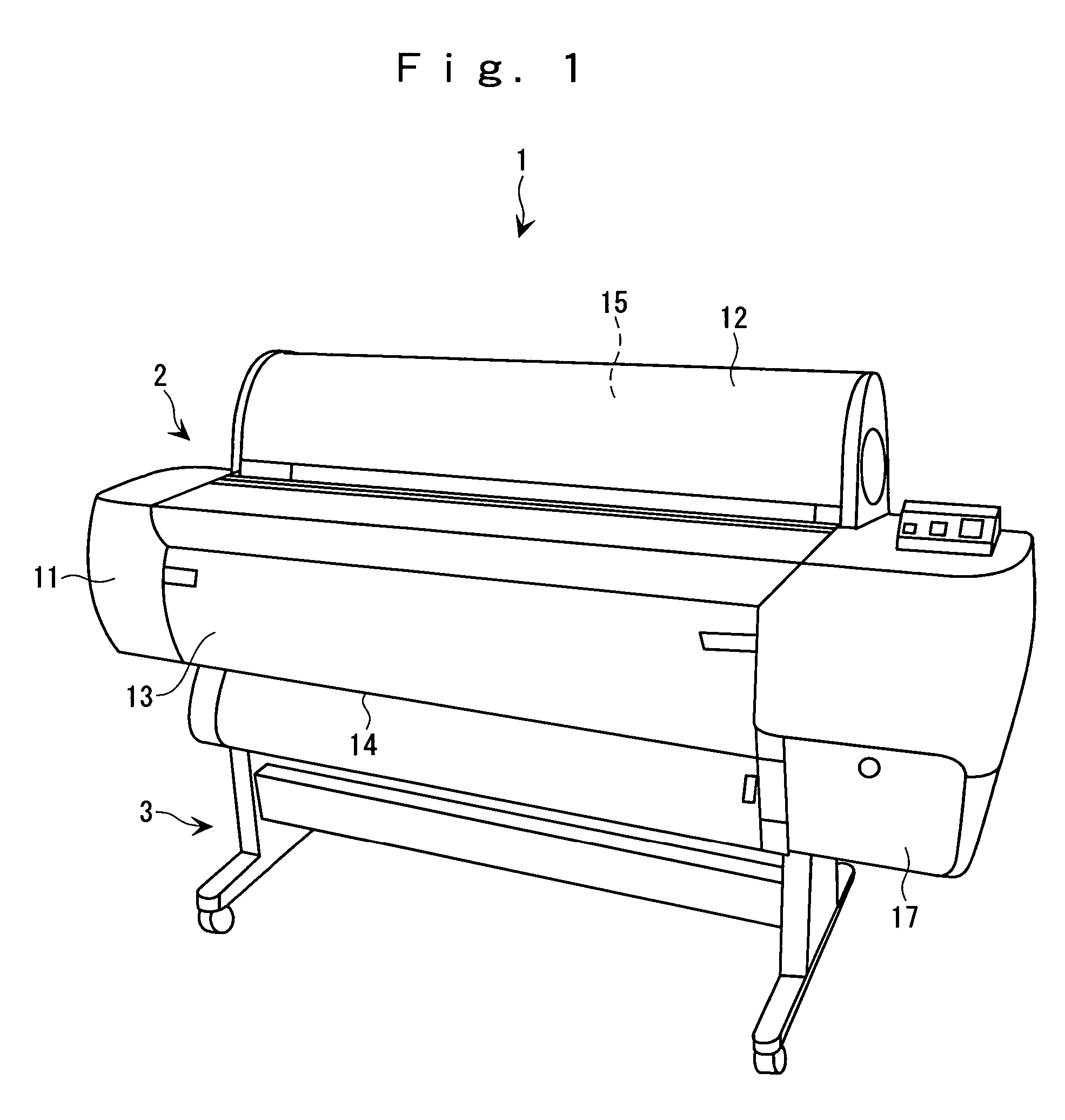
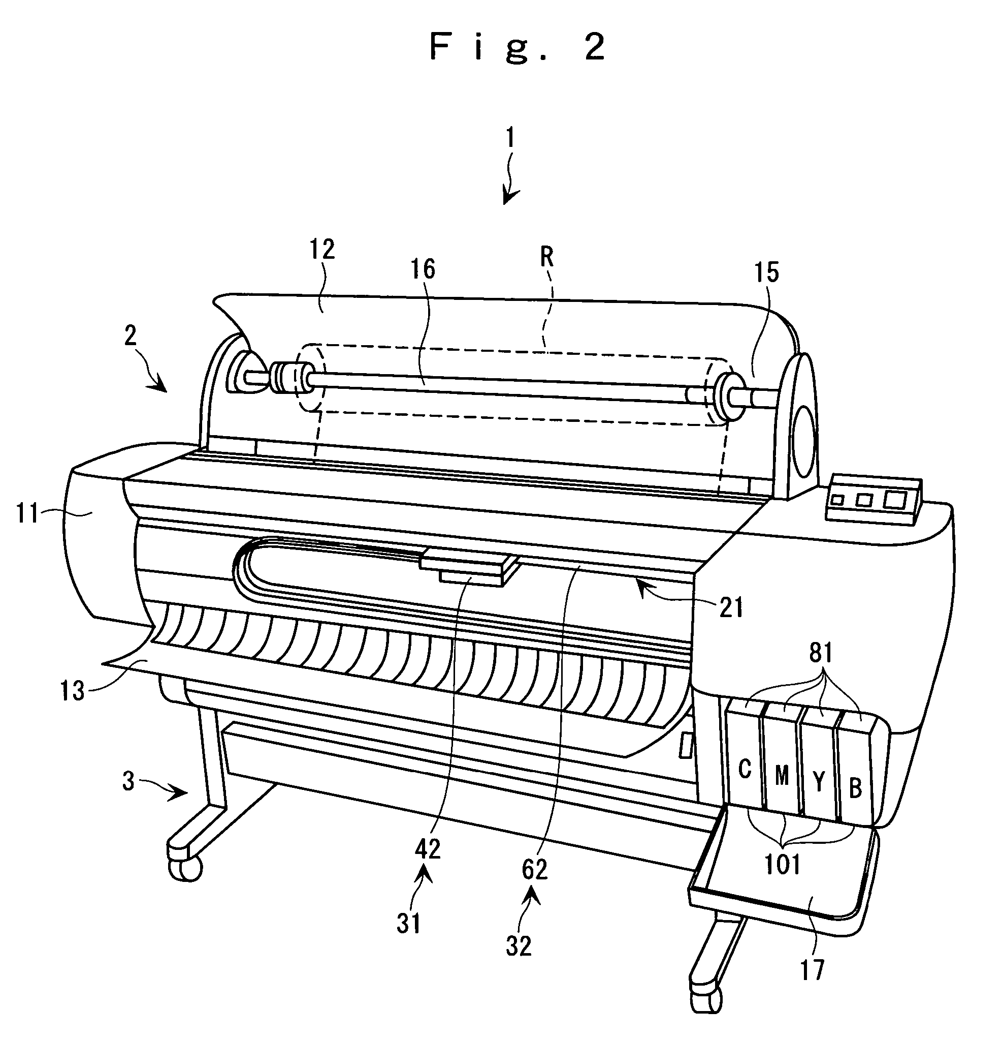
[0057]As shown in FIGS. 1 and 2, the ink jet printer 1 is made up of a printer main body 2 having an ink jet head 41 (to be described later), and a supporting stand 3 which supports the printer main body 2.

[0058]The printer main body 2 is covered on its outer frame with an apparatus casing 11 and is provided, on an upper rear portion thereof, with a roll-paper cover 12 for detachably mounting a r...

second embodiment

[0111]A description will now be made about the invention. The liquid droplet ejection apparatus is built into a so-called flat panel manufacturing line. A functional liquid of a functional material having dissolved therein a solvent is introduced into the functional liquid droplet ejection head. By using the liquid droplet ejection method (to which the ink jet method is applied), there is formed a coloring layer of a color filter in a liquid crystal display device made up of three colors of red (R), green (G) and blue (B), a light-emitting element forming each pixel of an organic electro-luminescence device, or the like.

[0112]As shown in FIG. 10, the liquid droplet ejection apparatus 201 is made up of: an apparatus base 202; an imaging apparatus 203 which is mounted on the entire area of the apparatus base 202 and which has a functional liquid droplet ejection head 252; a head maintenance apparatus 204 which is disposed in parallel with the imaging apparatus 203 on the apparatus bas...


PUM


Abstract

A method of controlling a liquid droplet ejection apparatus includes: a pressure detecting step of detecting whether the pressure inside a functional liquid tank is below a lower-limit pressure of a working pressure or not; a step of confirming, when the pressure inside the functional liquid tank is below the lower-limit pressure, whether a functional liquid droplet ejection head is in imaging operation or not; and a pressurization control step of, upon confirmation that the functional liquid droplet ejection head is not in imaging operation, pressurizing the functional liquid tank to an upper-limit pressure of the working pressure.

Description

[0001]The entire disclosure of Japanese Patent Application No. 2005-039494, filed Feb. 16, 2005 is expressly incorporated by reference herein.BACKGROUND[0002]1. Technical Field[0003]The present invention relates to: a method of controlling a liquid droplet ejection apparatus, the apparatus supplying a functional liquid droplet ejection head with a functional liquid under pressure from a functional liquid tank by pressurizing the functional liquid tank with a pressurizing pump to thereby maintain a predetermined working pressure, the apparatus also performing imaging operation by ejecting functional liquid droplets on an imaging target (or an object to which functional liquids droplets are discharged) set in an imaging region, the imaging being performed by driving the functional liquid droplet ejection head while relatively moving the functional liquid droplet ejection head and the imaging target; a liquid droplet ejection apparatus; a method of manufacturing an electro-optical devi...

Claims


Application Information

Patent Timeline
Patent Type & Authority Patents(United States)
IPC IPC(8): B41J2/175B41J2/195
CPCB41J2/17556B41J2/17546B41J2/07B41J29/393
Inventor USUDA, HIDENORIARUGA, KAZUMI
Owner KATEEVA
Why Eureka
Try Eureka