Concrete cooling injection unit and method of injecting a coolant into a concrete mixture

a concrete and injection unit technology, applied in clay preparation apparatus, chemistry apparatus and processes, transportation and packaging, etc., can solve the problems of large equipment and labor requirements for conventional approaches, low efficiency of concrete cooling injection, and high cost of methods

Active Publication Date: 2011-05-31
AIR LIQUIDE IND US LP
View PDF10 Cites 28 Cited by
  • Summary
  • Abstract
  • Description
  • Claims
  • Application Information

AI Technical Summary

Benefits of technology

[0013]Another embodiment provides a method for cooling a concrete mixture. The method consists of providing an injection system. Then adjusting an orientation of the lance relative to a concrete mixer. Then extending the lance to insert at least the injection nozzle into the concrete mixer. The method further consists of initiating a concrete cooling process comprising flowing a cooling fluid from the fluid source through the fluid path and out of the injection nozzle, whereby the cooling fluid is injected into the concrete mixer. At least one characteristic of the concrete cooling process is monitored to detect an endpoint of the concrete cooling process. The method further includes retracting the lance from the concrete mixer upon detecting the endpoint. The injection system has a support structure, a lance and a fluid source. The lance has a fluid path and an injection nozzle fluidly coupled to the fluid path. The lance is movably disposed on the support structure and being capable of movement relative to the support structure in at least one direction. The fluid source is fluidly coupled to the fluid path of the lance.

Problems solved by technology

If poured at high temperatures, set concrete will often not meet minimum strength requirements.
These methods are costly, time consuming and labor intensive.
The extensive equipment and labor required for conventional approaches pose various safety concerns such as back injuries from lifting ice, loss of limbs from operating ice crushers, etc.
Further, the use of ice can have a negative impact on the concretes characteristics, such as the slump measurement.
However, the injection processes used previously were cumbersome and expensive.
Prior injection systems were stationary injectors, which required time-consuming structural adjustments in order meet the requirements of different size mixers.
Further, the current injection systems are designed in a manner that increases the potential damage to the truck mixer drum.

Method used


Image

  • Concrete cooling injection unit and method of injecting a coolant into a concrete mixture
  • Concrete cooling injection unit and method of injecting a coolant into a concrete mixture
  • Concrete cooling injection unit and method of injecting a coolant into a concrete mixture

Examples


Embodiment Construction

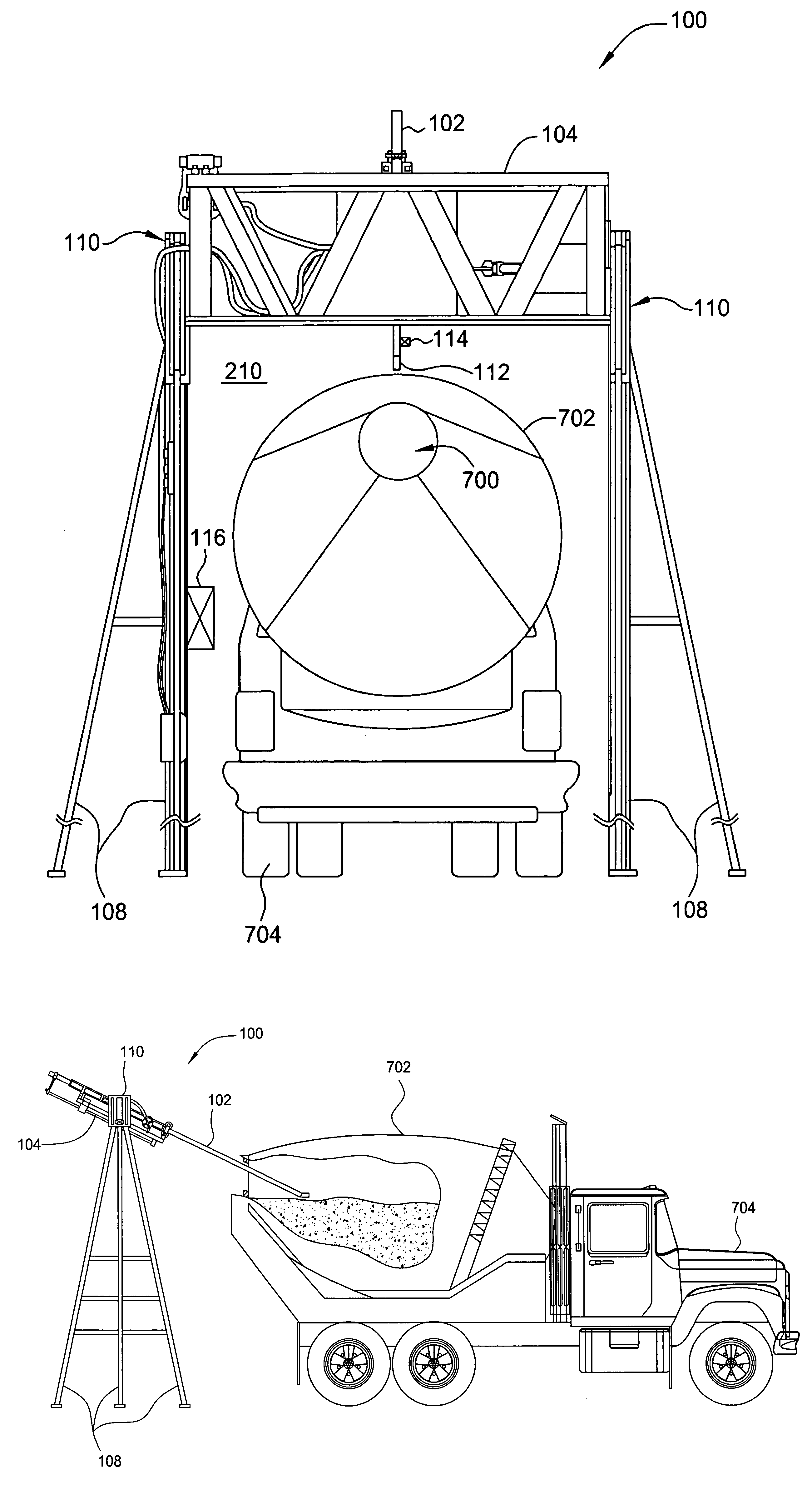
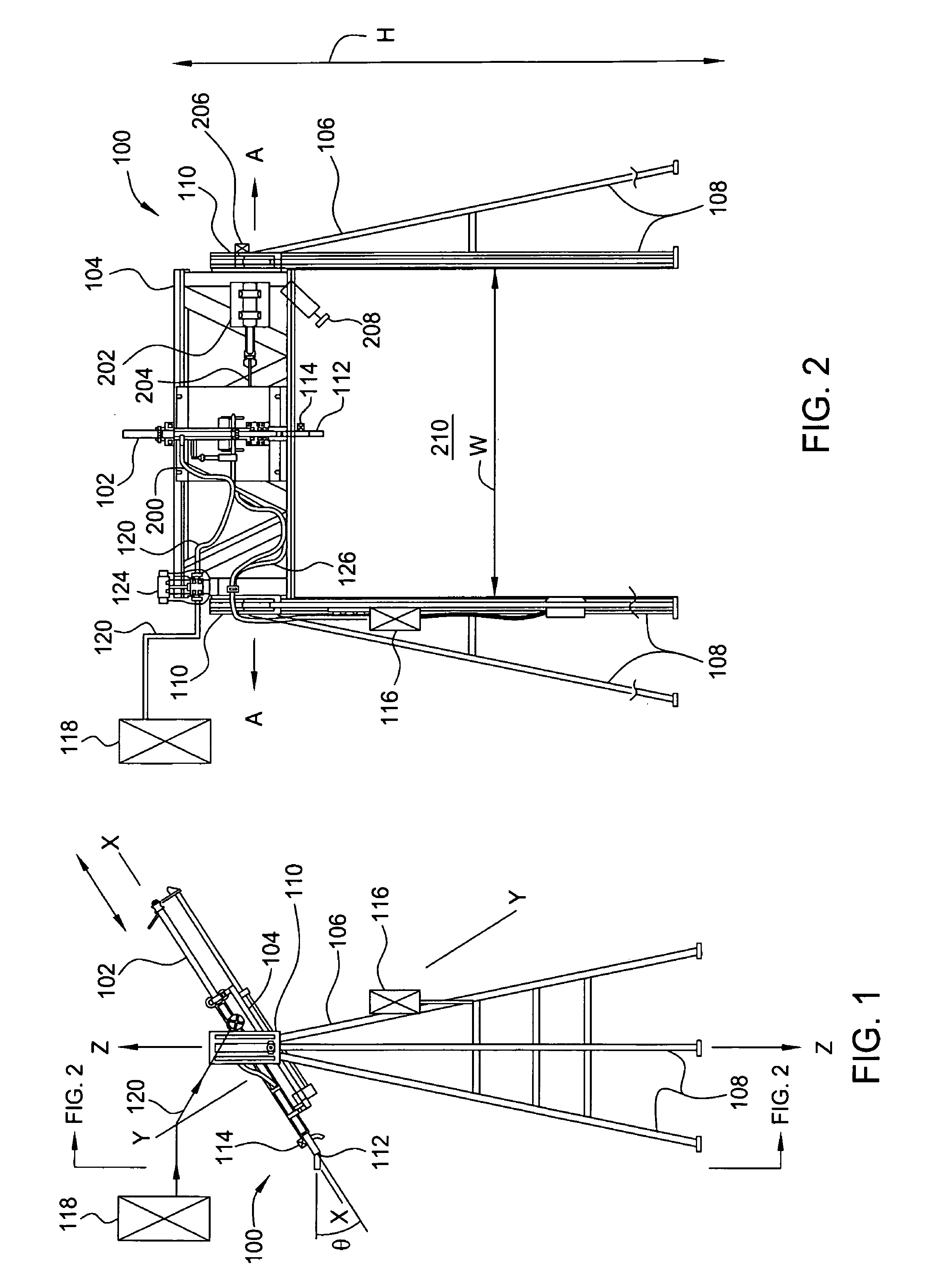
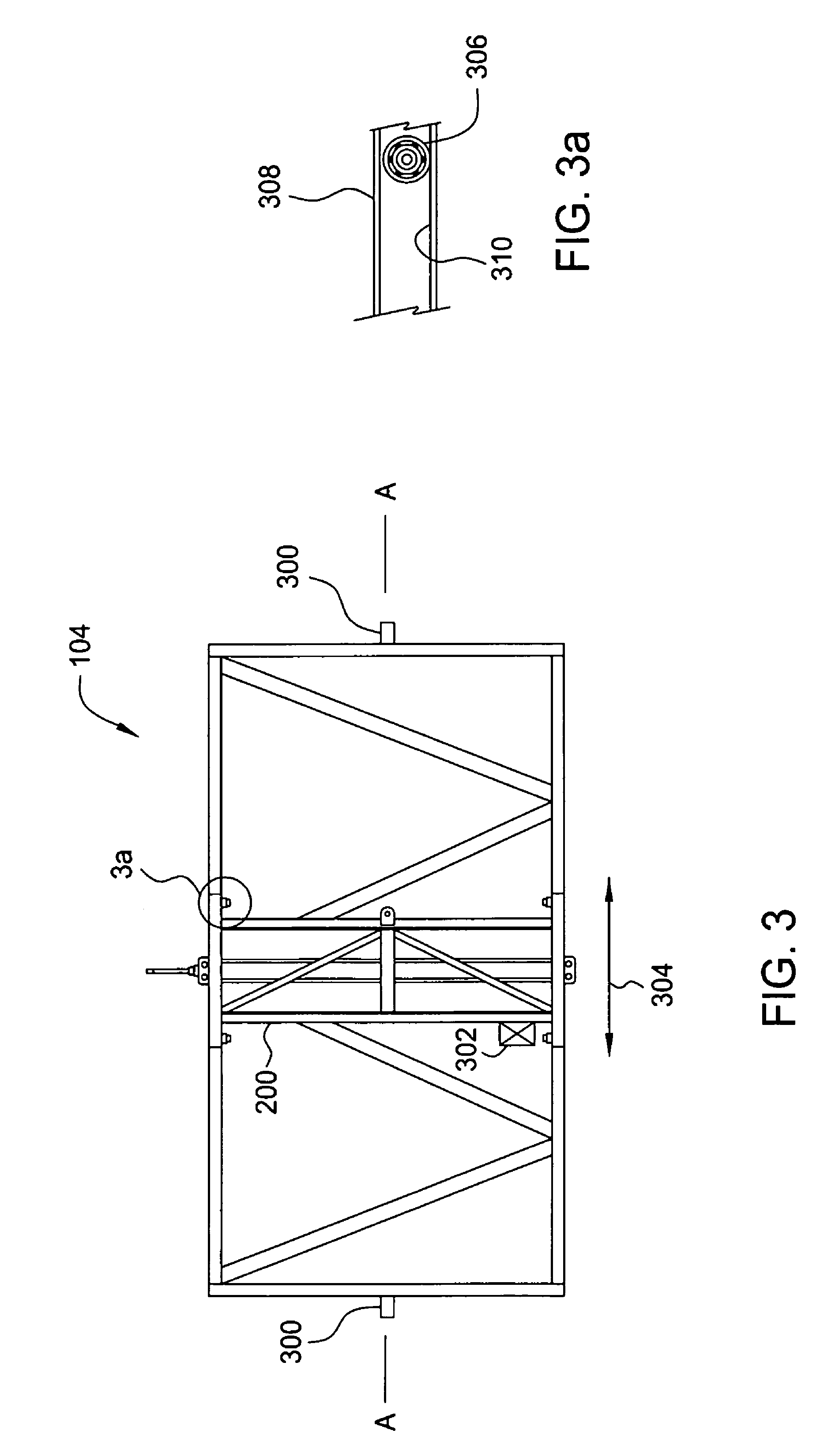
[0029]FIGS. 1 and 2 illustrate a side view and a front view, respectively, of an injection system 100, according to one embodiment of the invention. The injection system 100 includes a lance 102 configured to inject a fluid into a container (e.g., a concrete mixer 702, such as the one shown in FIG. 7). The lance 102 mounts to a carriage 200, shown in FIG. 2. The carriage 200 is disposed on a lance support assembly 104. The lance support assembly 104 is supported by a support structure 106. As shown, the support structure 106 consists of two sets of legs 108. Illustratively, there are three legs 108 for each support structure 106, however, it should be appreciated that any number of support legs 108 may be used. Further, there may be any number of support structures 106, including one leg. Further, as shown in FIG. 2, the two sets of legs 108 of the support structure 106 define an opening 210 having a height H and width W. In one embodiment, the size of the opening 210 is adjustable ...


PUM

PropertyMeasurementUnit
angleaaaaaaaaaa
movementaaaaaaaaaa
heightaaaaaaaaaa

Abstract

A method and apparatus for cooling a mixture with an injection system. The injection system is adjustable to accommodate the relative position and particular specifications of a given container (e.g., concrete mixer). In one embodiment, the injection system is operable to inject a coolant directly into the mixture while in the mixing process.

Description

CROSS-REFERENCE TO RELATED APPLICATIONS[0001]This application claims the benefit under 35 U.S.C. §119(e) to provisional application Ser. No. 60 / 655,975, filed Feb. 23, 2005, the entire contents of which are incorporated herein by reference.BACKGROUND[0002]1. Field of the Invention[0003]Embodiments of the present invention generally relate to an apparatus and method for cooling concrete. Particularly, the present invention relates to an apparatus and method for injecting a cryogenic liquid.[0004]2. Description of the Related Art[0005]In concrete preparation it is often necessary to cool the concrete mix. The structural integrity of concrete is dependent on the temperature at which the concrete is set. In general, the cooler the concrete when poured, the stronger it will be once set. If poured at high temperatures, set concrete will often not meet minimum strength requirements. This is especially true in warm weather climates (e.g., pours done in the summer).[0006]Traditionally, this ...

Claims


Application Information

Patent Timeline
Patent Type & Authority Patents(United States)
IPC IPC(8): B28C5/46B01F23/70
CPCB01F15/063B28C5/468B01F2015/061B01F2035/98B01F35/91
Inventor KLEIN, ERIC P.TEAS, DINO K.GARNETT, ANDREW M.
Owner AIR LIQUIDE IND US LP
Why Eureka
Try Eureka