System and method for improved rotary-wing aircraft performance with interior/external loads

a technology for rotary-wing aircraft and load management, applied in the direction of process and machine control, simultaneous indication of multiple variables, instruments, etc., can solve the problems of difficult to verify weight and location, time required to calculate aircraft weight and location, and often unavailabl

Inactive Publication Date: 2011-06-07
SIKORSKY AIRCRAFT CORP
View PDF46 Cites 35 Cited by
  • Summary
  • Abstract
  • Description
  • Claims
  • Application Information

AI Technical Summary

Problems solved by technology

Calculating an aircraft's C.G. may be a tedious manual process such that the time required to verify weights and locations, for example in a combat environment, is often unavailable.

Method used


Image

  • System and method for improved rotary-wing aircraft performance with interior/external loads
  • System and method for improved rotary-wing aircraft performance with interior/external loads
  • System and method for improved rotary-wing aircraft performance with interior/external loads

Examples


Embodiment Construction

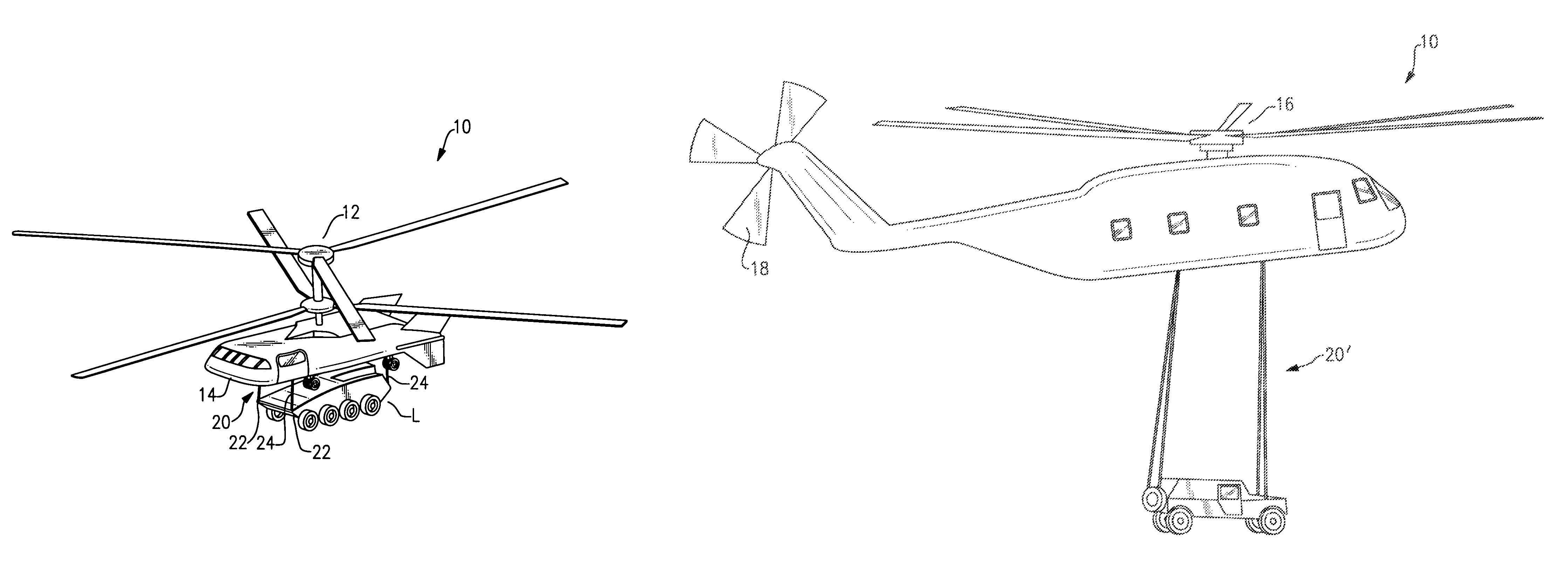
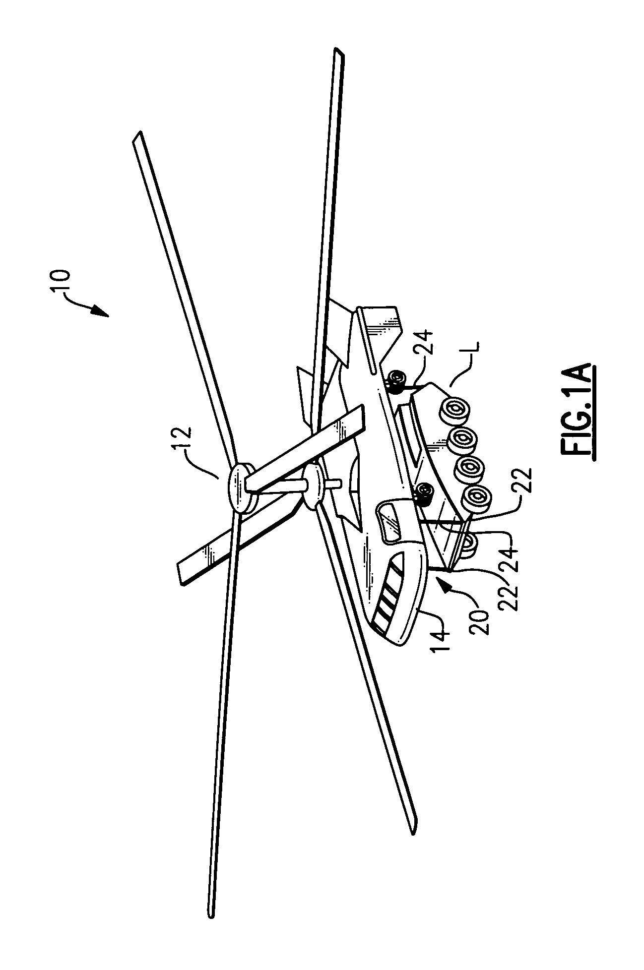
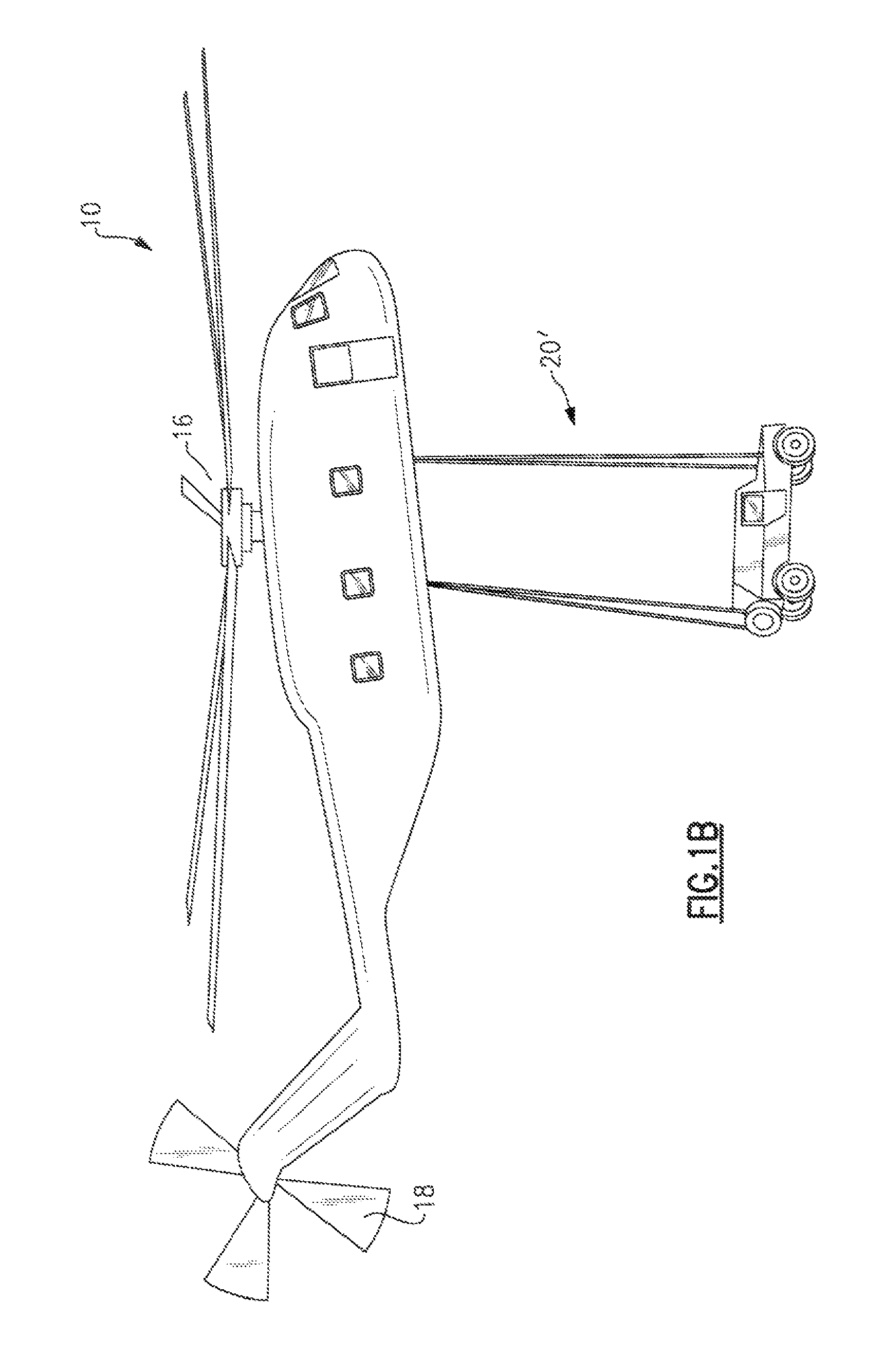
[0031]FIG. 1A schematically illustrates a rotary-wing aircraft 10 having a dual, counter-rotating, coaxial rotor system 12 mounted to a fuselage 14. The dual, counter-rotating, coaxial rotor system 12 includes an upper rotor system and a lower rotor system upon an essentially tailless fuselage which facilitates shipboard compatibility. Although a particular type rotary-wing aircraft configuration is illustrated in the disclosed embodiment, other aircraft such as conventional cargo aircraft, helicopters 10′ having a single main rotor assembly 16 and an anti-torque rotor 18 (FIG. 1B), flying cranes, tilt-rotor and tilt-wing aircraft will also benefit from the present invention.

[0032]An external load L is slung from the airframe 14 through a sling system 20 having a multitude of hoists 22 which deploy a cable 24 to the external load or loads L for attachment thereof. The cables 24 may be connected to the external load L or loads in any conventional manner.

[0033]Referring to FIG. 2, loa...


PUM


Abstract

An interactive aircraft load management system automates calculation and provides simulation capability to changes in an aircraft C.G. limit for display on a three-dimensional aircraft symbology. The aircraft load management system also communicates with a fly by wire (FBW) flight control system wherein the aircraft's control system is programmed to automatically compensate for C.G. excursions and to alter control laws. The aircraft load management system also selectively reels-in and reels out sling lines as the aircraft pitches and rolls to maintain a load vector from a slung load along the aircraft centerline. Load vector travel is accomplished by coupling a winch control system into the flight control system.

Description

BACKGROUND OF THE INVENTION[0001]The present invention claims the benefit of U.S. Provisional Patent Application No. 60 / 693,593, filed Jun. 24, 2005.[0002]This invention was made with government support under U.S. Navy Contract No. N00019-03-G-0003. The government therefore has certain rights in this invention.[0003]The present invention relates to a rotary-wing aircraft load management system, and more particularly to a system and method that calculates an aircraft's C.G. location and / or C.G. acceptable limits so that an aircrew can predict, simulate, and verify loads and C.G. information in real time.[0004]Vertical takeoff and landing (VTOL) rotary-wing aircraft are unique in their ability to carry loads externally. Future military forces require enhanced vertical lift capabilities in a compact package. Super heavy lift (SHL) rotary-wing aircraft are generally defined as an aircraft with twice the largest payload of current helicopters. Future requirements are envisioned to be in ...

Claims


Application Information

Patent Timeline
Patent Type & Authority Patents(United States)
IPC IPC(8): B64D47/00
CPCB64D1/22G05D1/0858G01M1/127G01D7/02G01D2207/10
Inventor BRAINARD, STEVEN J.HOUY, DAVID R.STOBIECKI, ANTHONY Z.SCOTT, MARK W.WEINER, STEVEN D.
Owner SIKORSKY AIRCRAFT CORP
Why Eureka
Try Eureka