Optical FSK/SSB modulator having intensity balance function

a technology of intensity balance and optical modulator, which is applied in the direction of light demodulation, instruments, electrical apparatus, etc., can solve the problems of preventing the extinction ratio from improving, and achieve the effect of suppressing non-desired components

Inactive Publication Date: 2011-06-07
NAT INST OF INFORMATION & COMM TECH
View PDF16 Cites 16 Cited by
  • Summary
  • Abstract
  • Description
  • Claims
  • Application Information

AI Technical Summary

Benefits of technology

[0018]The present invention is basically based on the following idea. The optical modulator includes an intensity modulator (12) arranged in a waveguide portion between a combining part of a first sub Mach-Zehnder waveguide (MZA) and a combining part (6) of the main Mach-Zehnder waveguide (MZC). The intensity modulator modulates intensity of an optical signal propagating through the waveguide portion. Signal intensity of components to be suppressed (e.g., a carrier component (f0) and a high order component (such as a second order component (f0±2fm)) of output signals from the respective sub Mach-Zehnder waveguide are adjusted to be the same level. Then, it is possible to effectively suppress the components to be suppressed (since phase is reversed) when the optical signals from the respective sub Mach-Zehnder waveguide are combined at the combining part (6).
[0025]The above arrangement of the present invention adjusts intensity levels of components to be suppressed (a carrier component (f0) and a high order component (e.g. a second order component (f0±2fm)) of output signals from each sub Mach-Zehnder waveguide to be about the same level. This enables to effectively suppress components to be suppressed when optical signals from each sub Mach-Zehnder are combined at the combining part.
[0031]The optical modulator according to the above embodiment is provided with the first main Mach-Zehnder electrode (MZCA electrode) (14) and the second main Mach-Zehnder electrode (MZCB electrode) (15). This configuration enables the optical modulator to control optical phase of an output signal from the each sub Mach-Zehnder waveguide, thereby suppressing carrier waves (carrier signals) or a high order component (e.g. a second order component (f0±2fm) of optical signals to be combined.
[0034]By using the optical modulator of this embodiment, it is possible to adjust bias voltage applied to each electrode adequately, thereby suppressing a carrier component (f0) and a high order component (e.g. a second order component (f0±2fm)) and realizing a higher extinction ratio.
[0036]The present invention enables to provide an optical modulator which is capable of adjusting optical intensity of optical signals which contains non-desired components so that the intensity of the components become at a similar level, whereby the optical modulator is capable of effectively suppressing the non-desired components when the optical signals are combined.

Problems solved by technology

However, in the actual output of an optical DSB-SC modulator, other than side band signals, there remain unsuppressed carrier components and high order component signals, preventing extinction ratio from improving.

Method used


Image

  • Optical FSK/SSB modulator having intensity balance function
  • Optical FSK/SSB modulator having intensity balance function
  • Optical FSK/SSB modulator having intensity balance function

Examples


second embodiment

4. Second Embodiment

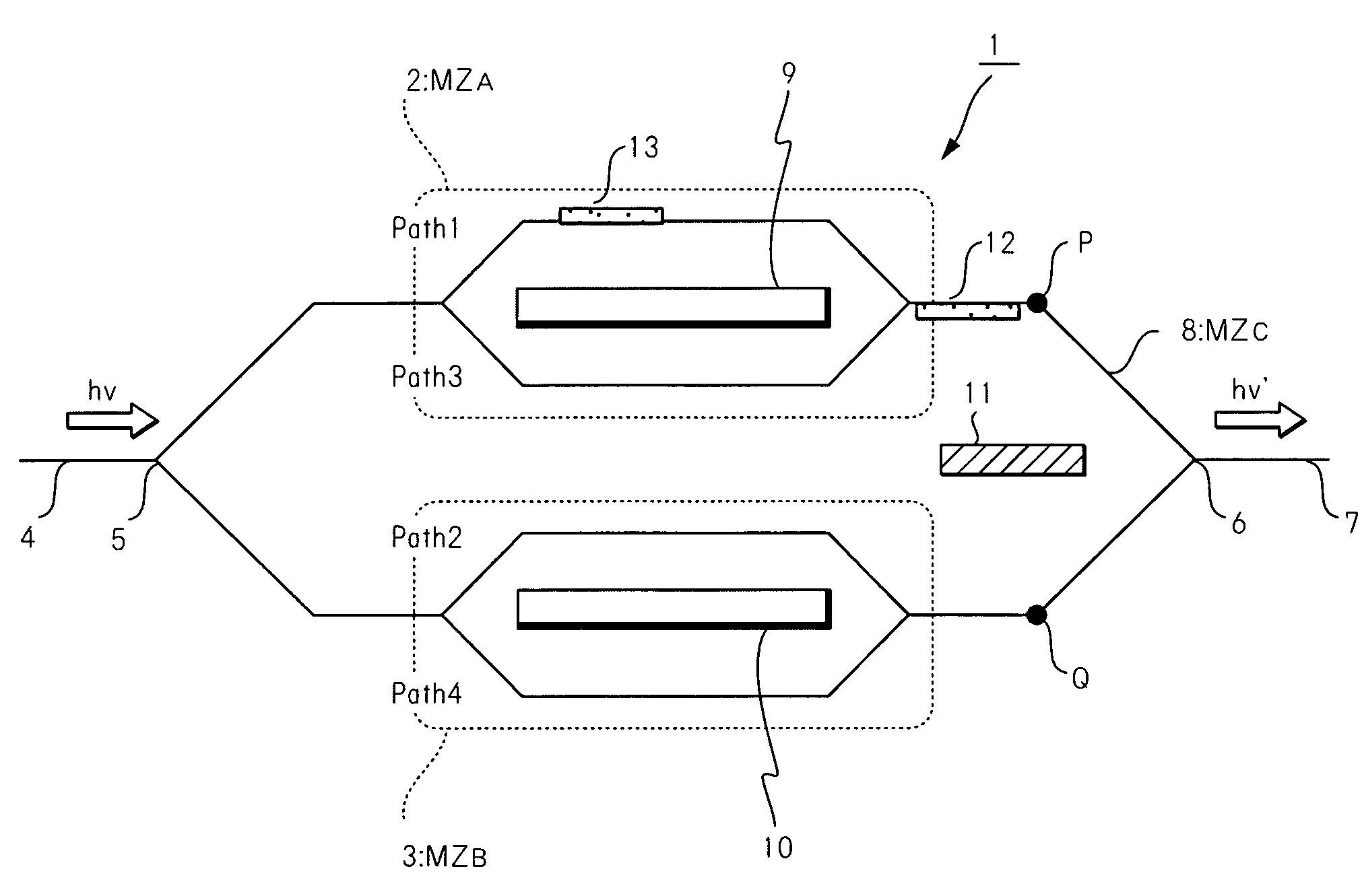
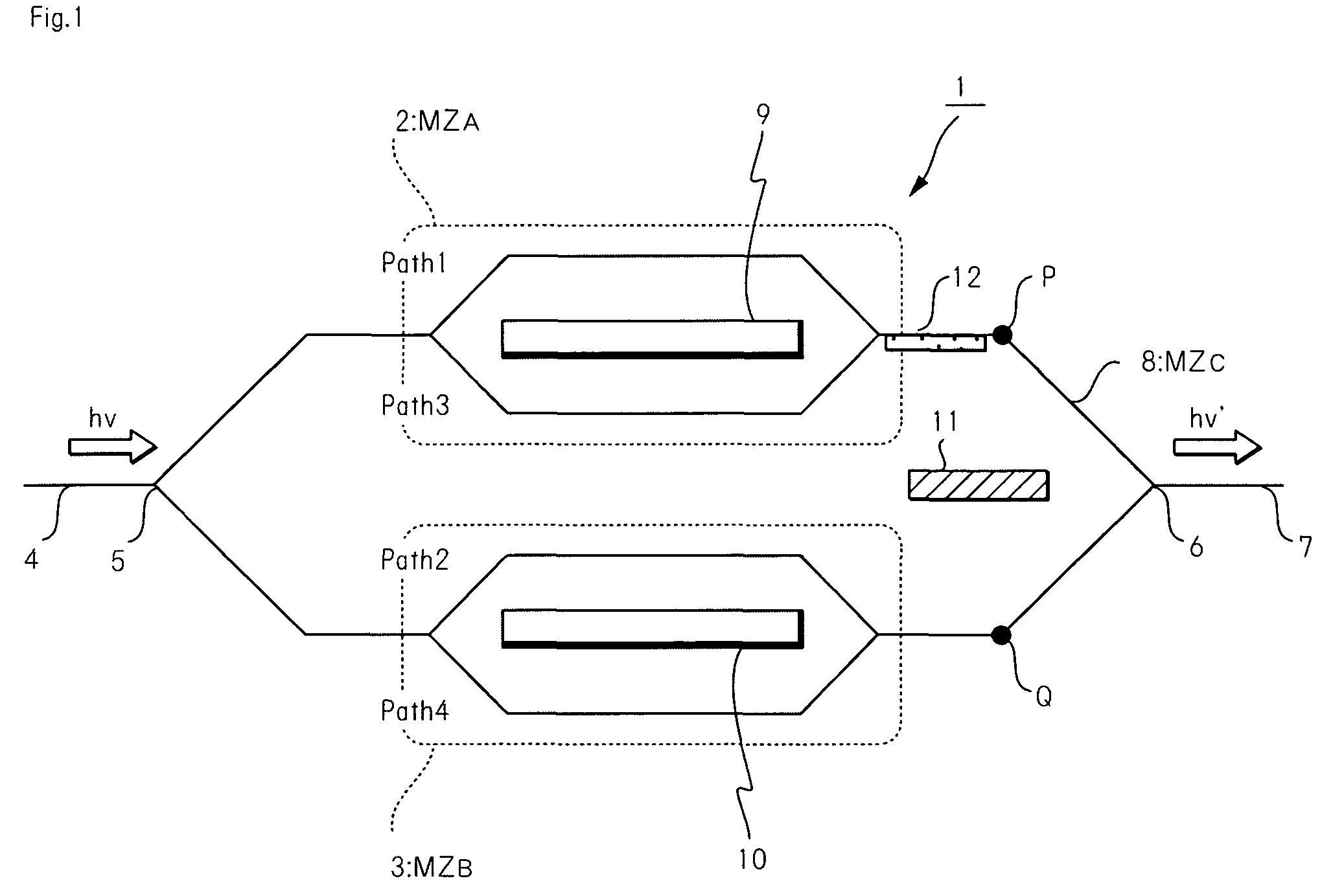
[0089]A preferable embodiment of the optical modulator is one further comprising an asymmetric directional coupler provided at the branching part (5) of the main Mach-Zehnder waveguide (MZC) (8). The asymmetric directional coupler controls intensity of the optical signal branched to the first sub Mach-Zehnder waveguide (MZA) so that the intensity of the optical signal branched to the first sub Mach-Zehnder waveguide (MZA) is higher than intensity of the optical signal branched to the second sub Mach-Zehnder waveguide (MZB).

[0090]If the intensity difference between components to be suppressed is small, the intensity modulator (12) is required to lessen the intensity of one of the component minutely. Further if optical intensity of an optical signal from the MZA is weaker than that from MZB, components to be suppressed cannot be effectively suppressed by the intensity modulator (12). On the contrary, the optical modulator described above can effectively use the int...

third embodiment

5. Third Embodiment

[0092]While not specifically shown in figures, the other preferable embodiment of the present invention is one further comprising the intensity modulator (12) provided on a waveguide portion between a combining part of the second sub Mach-Zehnder waveguide (MZB) and the combining part (6) of the main Mach-Zehnder waveguide (MZC). The intensity modulator modulates intensity of the optical signal propagating through the waveguide portion.

[0093]It is to be noted that an optical modulator further comprising the intensity modulator (12) provided on between the output part of the MZB and the combining part (6) is the other embodiment of the present invention. In this case, components desired to be suppressed can be adjusted and suppressed, regardless of which intensity is stronger between the optical signals from the MZA and the optical signal from the MZB.

fourth embodiment

6. Fourth Embodiment

[0094]FIG. 5 is a schematic block diagram showing an optical modulator according to the fourth embodiment of the present invention. As shown in FIG. 5, an optical modulator according to this embodiment further comprises an intensity modulator (13) provided on one of two arms composing the first sub Mach-Zehnder waveguide (MZA) or one of two arms composing the second sub Mach-Zehnder waveguide (MZB) or two or more of the waveguides. The intensity modulator (13) modulates intensity of the optical signals propagating through the waveguides

[0095]The arm (Path of FIG. 1) whereon the intensity modulator (13) is provided may be either one of Path1, Path2, Path3, or Path4. It may also be either one of Path1 and Path2, Path1 and Path3, or Path1 and Path4. It may also be either one of Path2 and Path3, or Path2 and Path4. It may also be Path3 and Path4. It may also be Path1, Path2 and Path3. It may also be Path1, Path2 and Path4. It may also be Path1, Path3 and Path4. It ma...


PUM

PropertyMeasurementUnit
widthaaaaaaaaaa
widthaaaaaaaaaa
thicknessaaaaaaaaaa

Abstract

It is an object of the present invention to provide an optical modulator which is capable of adjusting optical intensity of optical signals which contains non-desired components so that the intensity of the components become at a similar level, whereby the optical modulator is capable of effectively suppressing the non-desired components when the optical signals are combined.

Description

CROSS REFERENCE TO RELATED APPLICATION[0001]The present disclosure relates to subject matter contained in Japanese Patent Application No. 2005-242485 filed on Aug. 24, 2005, the disclosure of which is expressly incorporated herein by reference in its entirety.BACKGROUND OF THE INVENTION[0002]1. Field of the Invention[0003]The present invention relates to an optical modulator having intensity balance function, and the like. In particular, the present invention relates to an optical modulator and the like which is capable of adjusting optical intensity of optical signals which contains non-desired components so that the intensity of the components become at a similar level, whereby the optical modulator is capable of effectively suppressing the non-desired components when the optical signals are combined.[0004]2. Description of the Related Art[0005]In optical communication, light must be modulated to have signals. As optical modulation, direct modulation and external modulation are kn...

Claims


Application Information

Patent Timeline
Patent Type & Authority Patents(United States)
IPC IPC(8): H04B10/04G02F1/035H04B10/516H04B10/54H04B10/548H04B10/61
CPCG02F1/225H04B10/5563H04B10/5165H04B10/505
Inventor KAWANISHI, TETSUYAIZUTSU, MASAYUKISAKAMOTO, TAKAHIDETSUCHIYA, MASAHIRO
Owner NAT INST OF INFORMATION & COMM TECH
Why Eureka
Try Eureka