
Vibrating structure gyroscope

a gyroscope and vibration structure technology, applied in the direction of acceleration measurement using interia force, speed measurement using gyroscopic effects, electric/magnetic means, etc., can solve the problems of mems type gyroscope performance, bias and scalefactor stability, typical inadequate performance requirements of gyroscopes for such applications

Active Publication Date: 2011-06-14
ATLANTIC INERTIAL SYST
View PDF11 Cites 15 Cited by
  • Summary
  • Abstract
  • Description
  • Claims
  • Application Information

AI Technical Summary

Benefits of technology

[0005]The accuracy and stability of such a gyroscope, in terms of the scalefactor, is therefore dependent upon the accuracy of the primary pick-off transducer and the secondary drive transducer. Variations in the gain of either the primary pick-off transducer or the secondary drive transducer will directly affect the scalefactor. For the device described in WO2006006597, the gains of both the primary pick-off transducer and the secondary drive transducer are largely determined by the stability of capacitor gaps between the planar silicon ring and the individual transducer plates associated with the primary pick-off transducer or the secondary drive transducer. These gaps are known to vary over the operating temperature range of the gyroscope due to the thermal expansion of the various materials from which the device is manufactured. In order to minimise the effect of temperature induced variations in the capacitor gaps, it is desirable, where possible, to manufacture the gyroscope from selected materials that have low and well matched coefficients of thermal expansion. However, thermal expansion of such selected materials still give rise to a significant variation in the scalefactor, which in turn limits the performance level that can be achieved by the gyroscope.
[0009]According to an aspect of the invention, a vibrating structure gyroscope includes a semiconductor substrate, a vibrating planar ring structure, support means arranged to support the ring structure relative to the semiconductor substrate, the semiconductor substrate, ring structure and support means being arranged substantially co-planar with one another, at least one primary drive transducer arranged to cause the ring structure to oscillate in a primary mode at the resonant frequency of the primary mode, at least one primary pick-off transducer arranged to detect oscillation of the ring structure in the primary mode, at least one secondary pick-off transducer arranged to detect oscillation of a secondary mode induced when angular velocity is applied around an axis substantially perpendicular to the ring structure, at least one secondary drive transducer arranged to null the induced secondary mode oscillation, the primary and secondary drive transducers and the primary and secondary pick-off transducers all being arranged around the periphery of the ring structure and at least two oscillation frequency adjusting capacitor plates arranged around the periphery of the ring structure such that when a voltage is applied between at least one capacitor plate and the ring structure an electrostatic force is generated between the capacitor plate and the ring structure to differentially adjust the frequencies of the primary and secondary modes to reduce the difference between the frequencies of the primary and secondary modes, wherein at least one of the capacitor plates is located externally of the periphery of the ring structure and the other capacitor plate or capacitor plates are located internally of the periphery of the ring structure and at least one of the drive transducers or pick-off transducers are located internally of the periphery of the ring structure and the other drive transducer or drive transducers or pick-off transducer or pick-off transducers are located externally of the periphery of the ring structure.

Problems solved by technology

The performance requirements of gyroscopes for such applications are relatively undemanding, particularly when compared to typical aerospace and military applications, where gyroscopes are used for guidance and control.
The use of a MEMS type gyroscope in such demanding applications is relatively uncommon as a MEMS type gyroscope performance, in terms of the bias and scalefactor stability, is typically inadequate.
However, thermal expansion of such selected materials still give rise to a significant variation in the scalefactor, which in turn limits the performance level that can be achieved by the gyroscope.
However, small imperfections in the geometry of such a structure will typically give rise to a small residual frequency split between the primary carrier and secondary response mode frequencies.
However, practical limitations on the accuracy with which this phasing can be achieved means that some of the quadrature signal will typically remain to contaminate the true rotation induced in-phase signal.
This limitation is a major source of bias error for this type of gyroscope.

Method used


Image

  • Vibrating structure gyroscope
  • Vibrating structure gyroscope
  • Vibrating structure gyroscope

Examples


Embodiment Construction

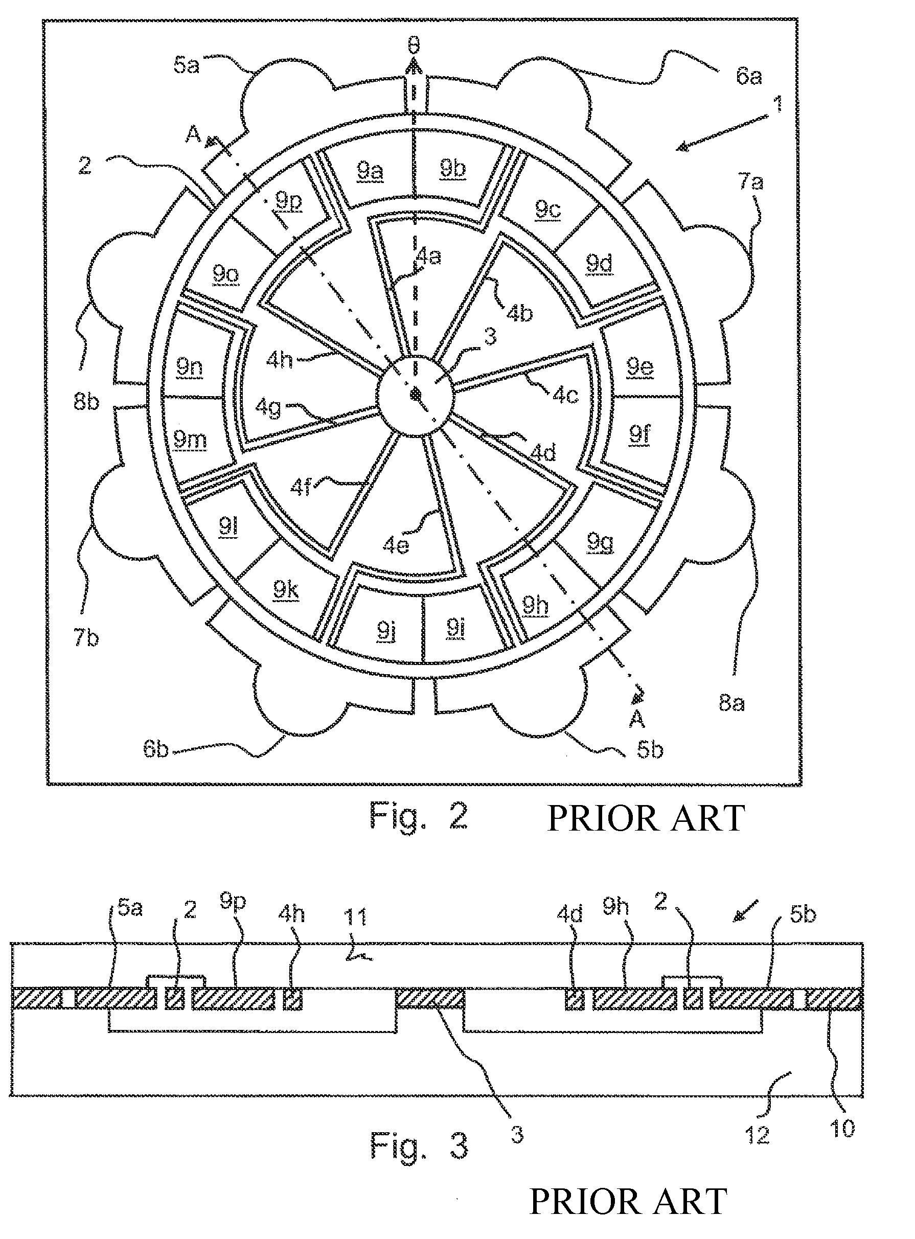
[0029]Referring to FIG. 2, a gyroscope structure 1 as described in WO20061006597 has a ring structure 2 supported from a central hub 3 by eight compliant support legs 4a to 4h. Drive transducers 5a, 5b, 6a and 6b and pick-off transducers 7a, 7b, 8a and 8b are all located around the outer circumference of the ring structure 2 and are each spaced from the ring structure 2 to create a capacitive gap. In closed loop operation, two opposed primary drive transducers 5a and 5b are used to excite the primary motion of the ring structure 2. Excited primary motion is detected by two opposed primary pick-off transducers 7a and 7b. Coriolis induced motion of the ring structure 2 is detected using two opposed secondary pick-off transducers 8a and 8b and such Coriolis induced motion is nulled using two opposed secondary drive transducers 6a and 6b. The gyroscope structure 1 includes sixteen capacitor plates 9a to 9p that are all located within the ring structure 2 and are each spaced from the rin...


PUM


Abstract

A gyroscope structure 41 includes ring structure 42 supported from a central hub 43 by eight compliant support legs 44a to 44h. Primary drive transducers 45a and 45b and secondary drive transducers 46a and 46b are all located around and in spaced relationship with the external periphery of the ring structure 42 to create capacitive gaps and primary pick-off transducers 47a and 47b and secondary pick-off transducers 48a and 48b are all located around and in spaced relationship with the internal periphery of the ring structure 42 to create capacitive gaps. The gyroscope structure 41 includes sixteen capacitor plates 49a to 49p in spaced relationship to the ring structure 42 to create capacitive gaps. Two groups of capacitive plates 49a to 49d and 49i to 49l are all located around the internal periphery of the ring structure 42 and two groups of capacitor plates 49e to 49h and 49m to 49p are all located around the external periphery of the ring structure 42. Each capacitor plate 49a to 49p is arranged to generate a predetermined electrostatic force, which acts upon the ring structure 42 to locally adjust the stiffness of the ring structure 42. The positioning of the transducers 45a to 48b and capacitor plates 49a to 49p reduces the effect of variation a capacitive gap with ring structure 42 due to temperature change, thereby improving the scalefactor of the gyroscope structure.

Description

[0001]This invention relates to a vibrating structure gyroscope, which is particularly, but not exclusively, suitable for use in a Coriolis type gyroscope constructed using Micro-Electro-Mechanical Systems techniques.[0002]Coriolis type gyroscopes, fabricated using Micro-Electro-Mechanical Systems (MEMS) technology, are now widely used for a range of high volume applications. For example, in the automotive industry such gyroscopes can be utilised in advanced braking systems, active suspension or rollover detection and prevention applications. The performance requirements of gyroscopes for such applications are relatively undemanding, particularly when compared to typical aerospace and military applications, where gyroscopes are used for guidance and control. The use of a MEMS type gyroscope in such demanding applications is relatively uncommon as a MEMS type gyroscope performance, in terms of the bias and scalefactor stability, is typically inadequate.[0003]The device described in W...

Claims


Application Information

Patent Timeline
IPC IPC(8): G01P9/04G01C19/5684
CPCG01C19/5684
Inventor FELL, CHRISTOPHER PAUL
Owner ATLANTIC INERTIAL SYST
Features
  • Generate Ideas
  • Intellectual Property
  • Life Sciences
  • Materials
  • Tech Scout
  • Unparalleled Data Quality
  • Higher Quality Content
  • 60% Fewer Hallucinations
Learn More