Tow bar

a technology of towed bars and towed parts, which is applied in the direction of towed devices, vehicle components, transportation and packaging, etc., can solve the problems of extremely limited ability of such a hitch combination to accommodate either pitch or roll, disastrous and even fatal consequences, and by itself provides absolutely no ability to accommodate any one of the three pitch, yaw or roll phenomena, and achieves reliable performance.

Inactive Publication Date: 2011-06-14
AUTOMATIC EQUIP MFG
View PDF22 Cites 17 Cited by
  • Summary
  • Abstract
  • Description
  • Claims
  • Application Information

AI Technical Summary

Benefits of technology

[0027]The principal objects and advantages of the present invention include: providing a tow bar structured to counteract the tendency of a towed vehicle to wander or fishtail which tendency operatively arises from the inherent play between a pintle and lunette ring hitch connection between towing and towed vehicles; providing such a tow bar wherein the tow bar legs are separately extendable and retractable as needed to accommodate the difference in span of each tow bar leg when connecting the tow bar legs to a towed vehicle hitching arrangement; providing such a tow bar having articulated tow bar leg connectors for connecting tow bar legs to a towed vehicle hitch arrangement; providing such a tow bar having a latching mechanism which, after connecting to a towed vehicle, separately and automatically locks the tow bar legs in a deployed configuration wherein the spans of the two bar legs are equal for towing purposes; providing such a tow bar having a cammed release mechanism for manually and toollessly unlocking the tow bar from the deployed configuration; providing such a tow bar wherein the tow bar legs have self-storing capability; providing such a tow bar having a latching mechanism which automatically and releasably latches the tow bar legs in a self-storing configuration; providing such a tow bar having a locking mechanism which is capable of latching the tow bar legs in either a self storing configuration or locking the tow bar legs in a deployed configuration wherein the spans of the tow bar legs are equal; and generally providing such a tow bar that is reliable in performance, capable of long-lasting life, and particularly well adapted for the proposed usages thereof.

Problems solved by technology

Although the ability of such a combination to accommodate yaw is acceptable and the pivot axis therefor is well-defined, unfortunately the ability of such a hitch combination to accommodate either pitch or roll is extremely limited.
Failure to strictly observe and properly accommodate such pitch and roll limitations can result in disastrous and even fatal consequences.
Although such an arrangement may be convenient for connecting a tow bar to a towing vehicle, this type of connection by itself provides absolutely no ability to accommodate any one of the three pitch, yaw or roll phenomena.
Unfortunately, this type of hitch arrangement inherently produces some play, although sometimes minimal, between the pintle and the lunette ring.
Such tendency to fishtail exacerbates wear and tear on the towing vehicle, on the towed vehicle, on the pintle, on the lunette ring, and on the pivotal connections between the tow bar legs and the tow bar head, which also visits greater stress on the operator of the towing vehicle while having to contend with such undesirable added activity between the towing and towed vehicles.
It is difficult, if not impossible, to perfectly align a towing vehicle with, and perfectly space the towing vehicle from, a towed vehicle so the tow bar legs can be easily and conveniently connected to the towed vehicle.
Such activity can be extremely stressful, sometimes requiring the efforts of more than one person, such as when connecting massive tow bars used for towing heavy military equipment for example.
Needless to say, such a method of storage can be very unsightly and may obstruct forward vision when the towed vehicle is subsequently being driven under its own power.
Also, this arrangement is not efficient for situations wherein the towing vehicle needs to use that tow bar to tow other vehicles.
Unfortunately, it is not uncommon for such arrangements to become unhooked, especially when the towing vehicle travels over very rough terrain, such as railroad tracks, potholes, and the like.

Method used


Image

  • Tow bar
  • Tow bar
  • Tow bar

Examples


Embodiment Construction

[0048]As required, embodiments of the present invention are disclosed herein; however, it is to be understood that the disclosed embodiments are merely exemplary of the invention, which may be embodied in various forms. Therefore, specific structural and functional details disclosed herein are not to be interpreted as limiting, but merely as a basis for claims and as a representative basis for teaching one skilled in the art to variously employ the present invention in virtually any appropriately detailed structure.

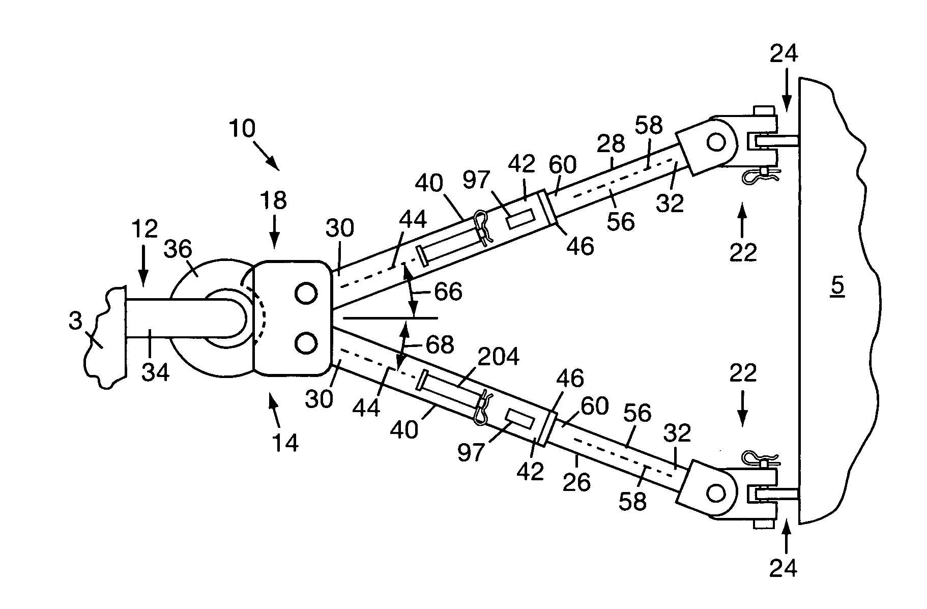
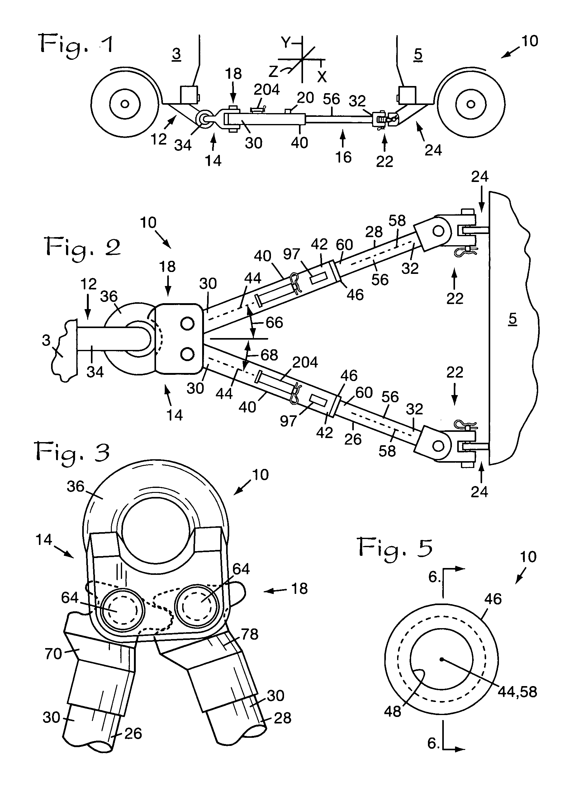
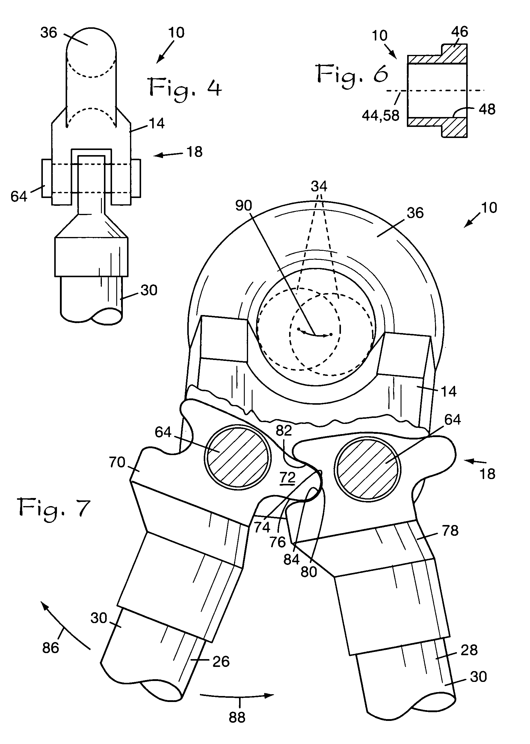
[0049]A tow bar typically connects the rear end of a towing vehicle 3 to the front end of a towed vehicle 5. The reference numeral 10 refers to a tow bar in accordance with the present invention, as shown in FIGS. 1 through 17. The tow bar 10 includes a towing hitch member 12, a head member 14, at least one tow bar leg 16, fore leg connector mechanism 18, latching mechanism 20, aft leg connector mechanisms 22, and a towed vehicle hitch member 24.

[0050]The following descri...


PUM


Abstract

A tow bar including a pintle hitch, telescoping tow bar legs pivotally connected to a head member, a lunette ring fixedly or pivotally connected to the head member, leg connector mechanisms releasably connecting the tow bar legs to a vehicle to be towed, and a latching mechanism including latching portions structured to releasably retain the tow bar legs in a stored configuration and locking portions with cammed release mechanisms wherein the locking portions are structured to releasable lock the tow bar legs in a deployed configuration.

Description

BACKGROUND OF THE INVENTION[0001]1. Field of the Invention[0002]The present invention relates to towing accessories and more particularly without limitation, to tow bars for connecting a towing vehicle to a vehicle to be towed.[0003]2. Description of the Related Art[0004]A tow bar is generally used for connecting a towing hitch arrangement of a towing vehicle to a towing hitch arrangement of a vehicle to be towed, sometimes referred to herein as a towed vehicle. For tow bar applications wherein heavy, massive equipment will be moved a relatively short distance, such as where an airliner is to be backed away from a terminal for example, the tow bar generally has only one tow bar leg. For such applications, one end of the tow bar leg may be connected to the front end of the vehicle to be moved and the other end of the tow bar leg connected to the front end of the moving vehicle so the operator of the towing vehicle can face the vehicle to be moved and can carefully observe the respons...

Claims


Application Information

Patent Timeline
Patent Type & Authority Patents(United States)
IPC IPC(8): B60D1/54
CPCB60D1/04B60D1/54B60D1/167
Inventor HUSTON, JAMESMERCHANT, DAVIDGOODMAN, STEVENROEBER, LESLIEWAGNER, NEIL
Owner AUTOMATIC EQUIP MFG
Why Eureka
Try Eureka