Liquid state detecting sensor

Inactive Publication Date: 2011-06-14
NGK SPARK PLUG CO LTD
View PDF12 Cites 9 Cited by
  • Summary
  • Abstract
  • Description
  • Claims
  • Application Information

AI Technical Summary

Benefits of technology

[0011]The present invention has been made in view of the above-described problems, and an object thereof is to provide a liquid state detecting sensor having a liquid concentration detecting element for detecting the concentration of a particular component in a liquid, which sensor is capable of appropriately discharging bubbles which have entered an enclosed measurement region, to thereby reduce the effect of the bubbles on the concentration measurement.
[0012]Another object of the invention is to provide a liquid state detecting sensor having an enclosing member and an outer enclosing member, which sensor is capable of appropriately discharging bubbles which have entered between the enclosing member and the outer enclosing member, to thereby reduce the effect of the bubbles on the concentration measurement.

Problems solved by technology

However, even in the case where a urea aqueous solution of the prescribed concentration is accommodated in a urea tank for storing the urea aqueous solution, there are cases where the urea concentration changes over time.
In addition, there may be instances where a liquid other than the urea aqueous solution of the proper urea concentration, such as service water, is erroneously poured into the urea tank.

Method used


Image

  • Liquid state detecting sensor
  • Liquid state detecting sensor
  • Liquid state detecting sensor

Examples


first embodiment

[0149]Referring to FIGS. 1 to 11, a description will be given of an embodiment of a liquid state detecting sensor in accordance with the invention. However, the present invention should not be construed as being limited thereto.

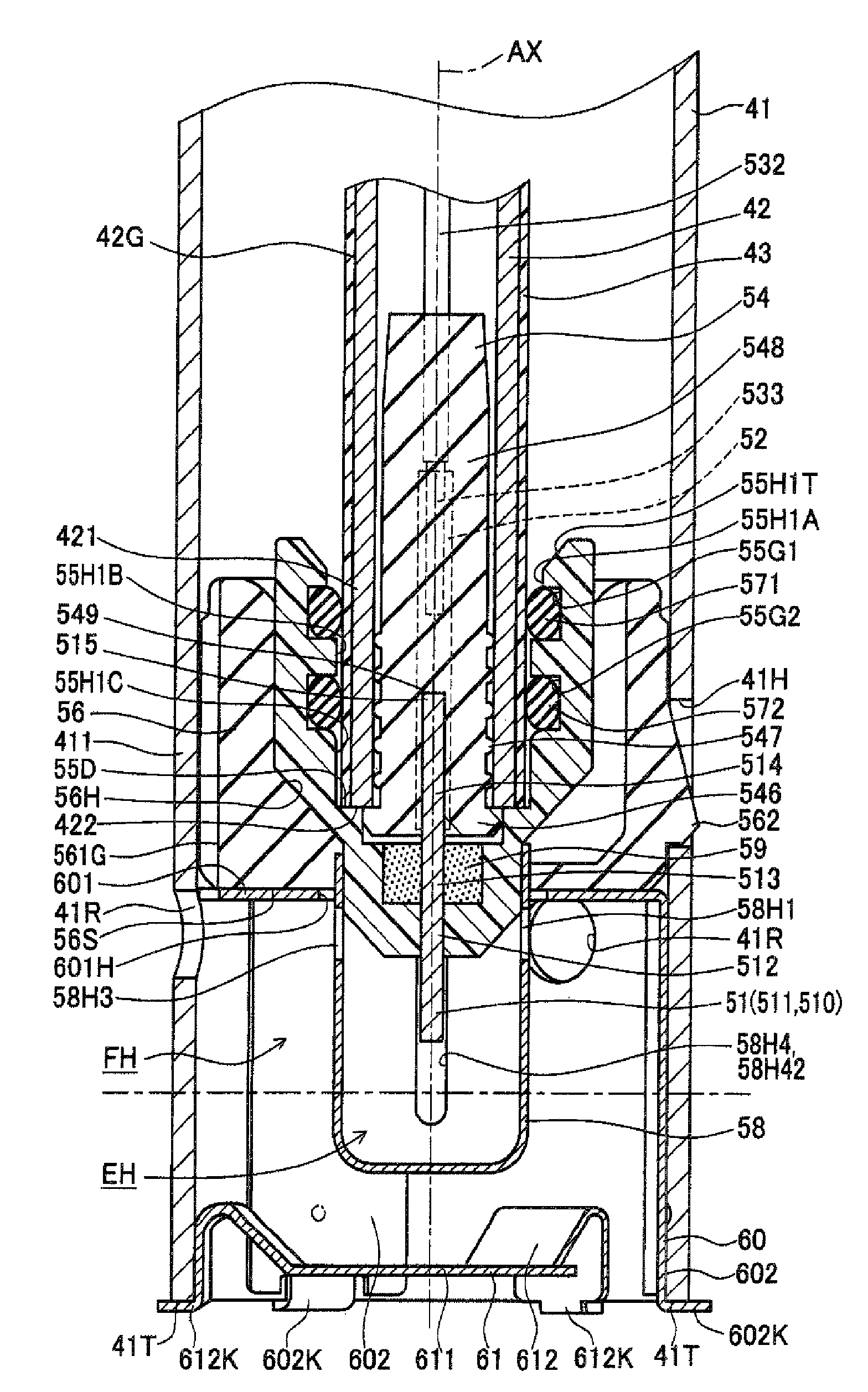
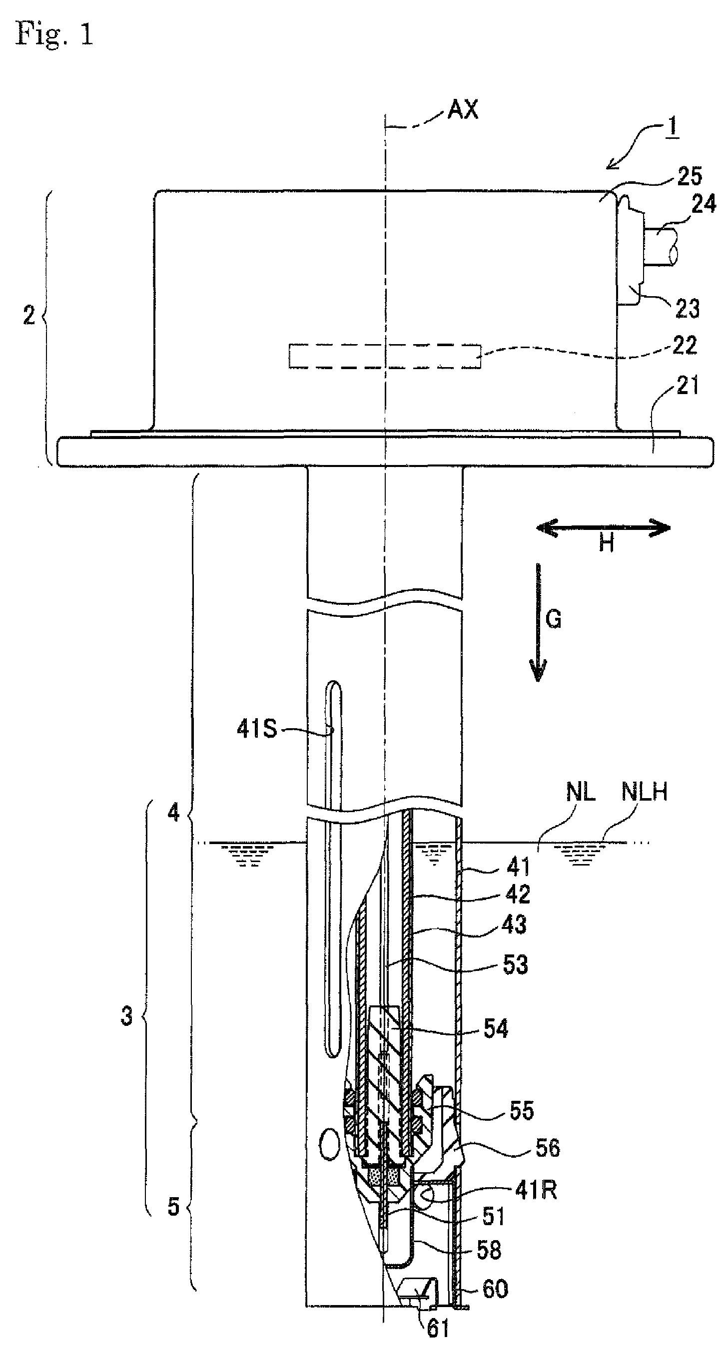
[0150]A liquid state detecting sensor 1 (hereafter also referred to as the sensor) in accordance with the first embodiment is used as a device for detecting the concentration of an urea aqueous solution NL accommodated in an accommodation tank and for detecting the liquid level NLH of the urea aqueous solution NL in an exhaust gas purifying apparatus for reducing and rendering harmless nitrogen oxides (NOx) emitted from a diesel engine, e.g., a motor automobile with a diesel engine mounted thereon, by the urea aqueous solution NL.

[0151]This liquid state detecting sensor 1 is comprised of a proximal portion 2 and a sensor portion 3 extending downward in FIG. 1 from the proximal portion 2. The liquid state detecting sensor 1 is used by mounting the proximal por...

second embodiment

[0243]Next, referring to FIGS. 14 to 21D, a description will be given of a second embodiment of the invention. A sensor 2001 in accordance with the second embodiment differs from the above-described first embodiment only in that the respective shapes of the holder member, the rubber bushing, the protector, the positioning member, and the rectifying member slightly differ. Therefore, a description will be given centering on differing portions, and a description of similar portions will be omitted or simplified.

[0244]The liquid state detecting sensor 2001 (see FIG. 14) in accordance with the second embodiment is used as a device for detecting the concentration of the urea aqueous solution NL accommodated in the accommodation tank and for detecting the liquid level NLH of the urea aqueous solution NL. In the same way as in the first embodiment, the liquid state detecting sensor 2001 includes proximal portion 2 and a sensor portion 3 extending therefrom downward in the drawings. Proxima...


PUM


Abstract

A liquid state detecting sensor for detecting a state of a liquid including a liquid concentration detecting element, a holder member, and an enclosing member as defined herein, wherein the holder member has a configuration in which respective portions of a lower end surface facing the enclosed region are located higher than or at a same height as a lowest hole periphery at the rim of the element holding hole from which the detecting element protrudes, and at least one of circulation holes formed in the enclosing member is a bubble-discharging hole which has an upper end located higher than the lowest hole periphery and a lower end located lower than a surface peripheral edge of the lower end surface.

Description

BACKGROUND OF THE INVENTION[0001]1. Field of the Invention[0002]The present invention relates to a liquid state detecting sensor for detecting the state of a liquid, and more particularly to a liquid state detecting sensor having a liquid concentration detecting element for detecting the concentration of a particular component in a liquid.[0003]2. Description of the Related Art[0004]In recent years, there are cases where an NOx selective reduction catalyst (SCR) system is used in an exhaust gas purifying apparatus for reducing and rendering harmless nitrogen oxides (NOx) emitted from a diesel engine, e.g., a motor automobile with a diesel engine mounted thereon. In this system, a urea aqueous solution is used as a reducing agent, but in order to effectively reduce the nitrogen oxides in this system, the concentration of urea in the urea aqueous solution is necessarily controlled within a prescribed range.[0005]However, even in the case where a urea aqueous solution of the prescribed...

Claims


Application Information

Patent Timeline
IPC IPC(8): G01N15/06G01N25/00G01F23/00
CPCG01F23/268F01N11/00F01N2900/1818F01N2550/05
Inventor YAMAMOTO, TAKASHISATO, YOSHIKUNISASANUMA, TAKEOYOSHIDA, AKIHIRO
Owner NGK SPARK PLUG CO LTD
Why Eureka
Try Eureka