Luminous switch and electronic device provided with the same

a technology of electronic devices and luminous switches, applied in the direction of contact surface shapes/structures, emergency actuators, moving contacts, etc., can solve problems such as affecting the uniformity of switch illumination, and achieve the effect of reducing acoustic nois

Inactive Publication Date: 2011-06-14
NEC CORP
View PDF13 Cites 10 Cited by
  • Summary
  • Abstract
  • Description
  • Claims
  • Application Information

AI Technical Summary

Benefits of technology

[0022]In the luminous switch of the present invention, the supporting sections are formed in the form of dot-like members, that is, the interval (inner dimension) between the supporting sections is larger than the width of the elastic member in both the longitudinal and lateral directions. With this structure, it is possible to reduce the acoustic noise due to the inorganic EL illumination. Further, due to the provision of the supporting sections, the frequency band is shifted so as to achieve an increase in natural frequency, making the acoustic noise almost inaudible to the human ear.

Problems solved by technology

However, it should be noted that the thinning tends to impair uniformity of switch illumination.

Method used


Image

  • Luminous switch and electronic device provided with the same
  • Luminous switch and electronic device provided with the same
  • Luminous switch and electronic device provided with the same

Examples


first embodiment

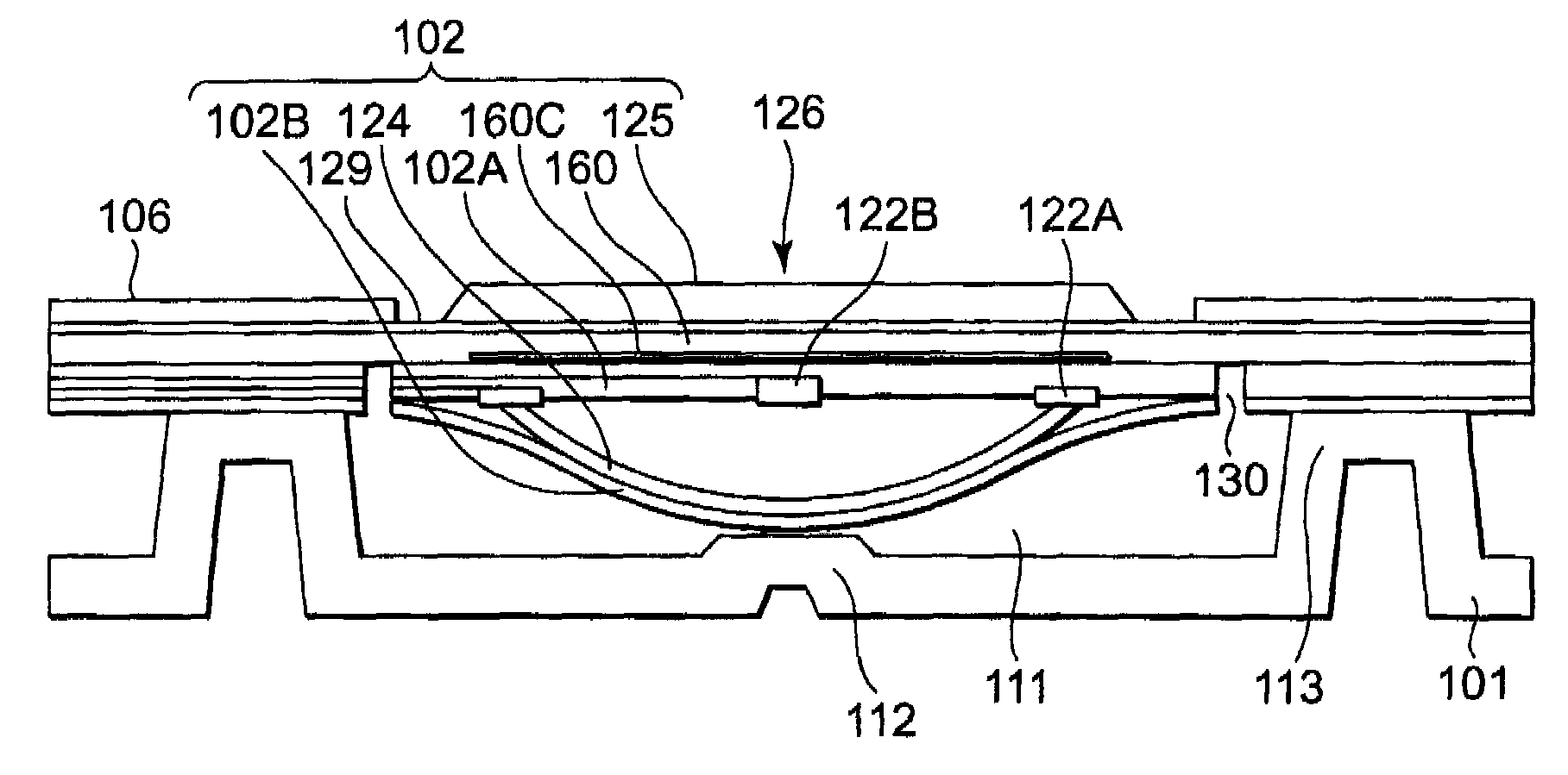
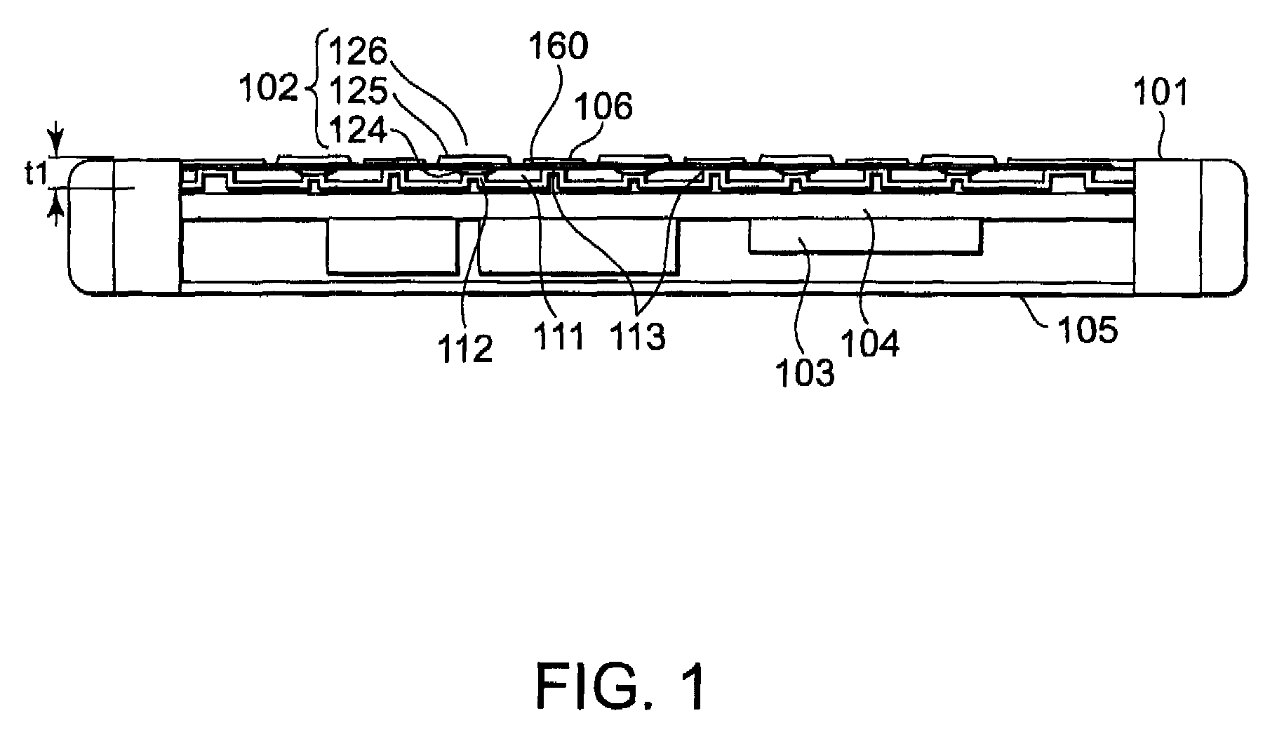
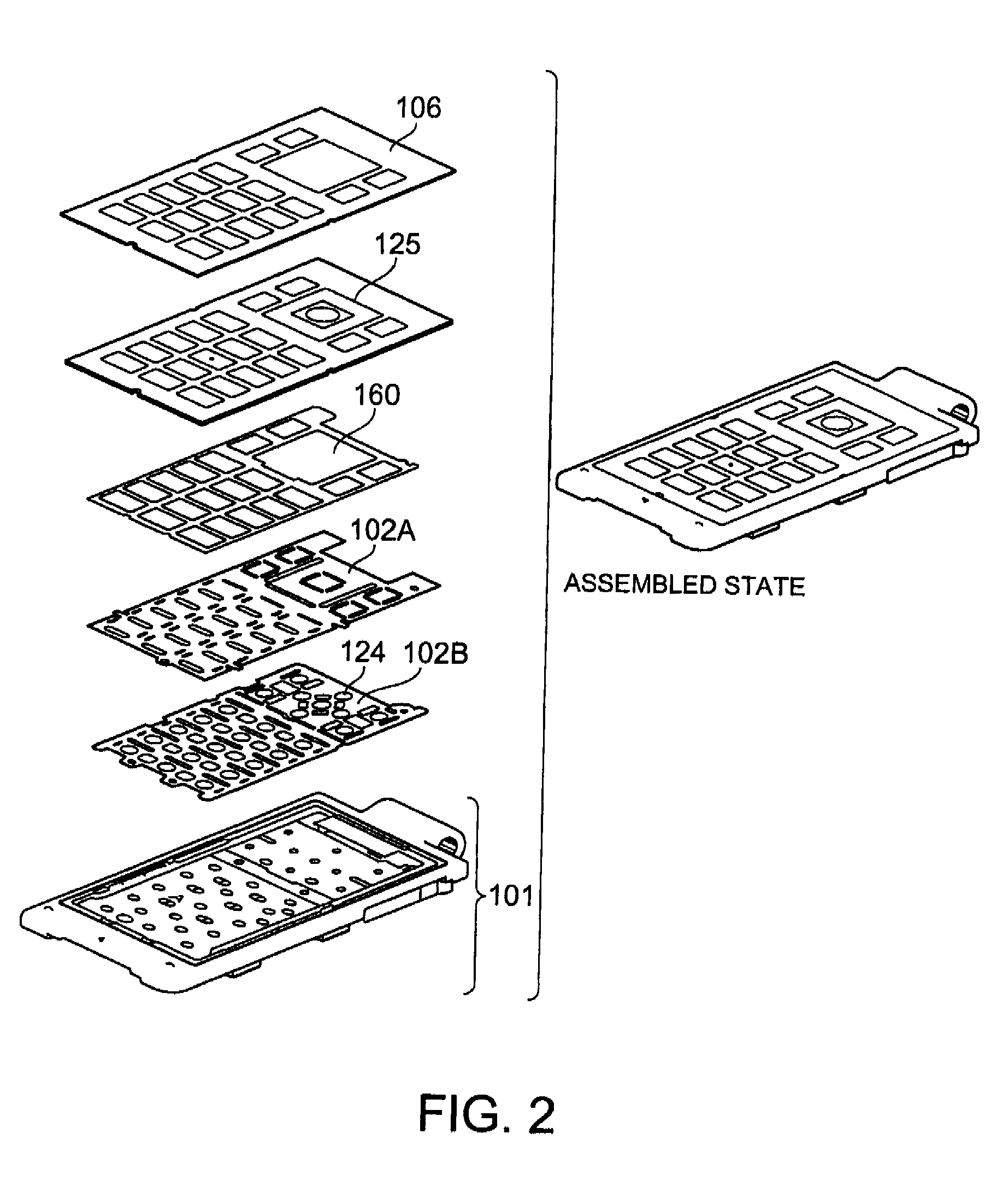
[0046]FIG. 1 is a sectional view of a luminous switch according to an embodiment of the present invention. FIG. 2 is an exploded perspective view of the luminous switch, and FIG. 3 is a sectional view of one pushbutton switch of the luminous switch.

[0047]As shown in FIGS. 1 and 2, the luminous switch of the present invention has a plurality of protruding parts 112 and a plurality of supporting sections 113 both of which are formed on a surface of a structure 101. Further, as is apparent from FIG. 3, which is a sectional view of a switch section of FIG. 1, a plurality of switch sections each include a conductor 124 which is elastically deformable and which is arranged so that its convex surface is opposed to the protruding part 112, a wiring sheet 102A covering each conductor 124, a luminous sheet 160 covering the wiring sheet 102A, and a plurality of switch buttons 125 arranged above the luminous sheet 160.

[0048]At least two supporting sections 113 are provided around each protrudin...

second embodiment

[0070]Next, a second embodiment would be described. FIG. 8 is an exploded perspective view of the switch sheet 102 of a luminous switch according to the second embodiment of the present invention. The second embodiment differs from the first embodiment in that the luminous sheet 160, the wiring sheet 102A, and the cover sheet 102B are integrated by gluing them to each other.

[0071]More specifically, as shown in FIGS. 8 and 14, an adhesive material 1401 is provided on the luminous sheet 160 side surface of the wiring sheet 102A. Further, as shown in FIG. 14, the adhesive material 1401 is provided substantially all over one surface of the wiring sheet 102A. On the other hand, as shown in FIG. 15, an adhesive material 1402 is provided on the wiring sheet 102A side surface of the cover sheet 102B, and the adhesive material 1402 is also provided substantially all over one surface of the wiring sheet 102B. As described above, the adhesive materials 1401 and 1402, which are provided substan...

third embodiment

[0074]Next, a third embodiment would be described. FIG. 9 is an exploded sectional view of the structure 101 of a luminous switch according to the third embodiment of the present invention. The third embodiment differs from the first embodiment in that the region of the structure 101 for the protruding parts 112 and the supporting sections 113 is formed of metal, and the peripheral region thereof is formed of resin.

[0075]More specifically, a first casing 1011 is first formed of metal, and then the first casing 1011 is installed in another mold, into which resin is poured to form a second casing 1012, whereby the first casing 1011 and the second casing 1012 are integrally molded. In this case, the first casing 1011 is formed by press molding of sheet metal or casting of magnesium, aluminum or the like. On the other hand, the resin of the second casing 1012 is selected taking into account a plurality of factors such as strength, drop impact property, and moldability.

[0076]Instead of i...


PUM


Abstract

A luminous switch using an inorganic EL material is provided with a plurality of switch sections so as to reduce acoustic noise. The switch sections are provided with a plurality of protruding parts (112) and a plurality of supporting sections (113) formed on a surface of a structure (101); an elastic deformable conductor (124) arranged to have a convex surface opposed the protruding parts (112); a wiring sheet (102A) for covering the conductor (124); a luminous sheet (160) for covering the wiring sheet (102A); and a plurality of switch buttons (125) arranged above the luminous sheet (160). The luminous switch has a structure in which at least two supporting sections (113) are arranged around the protruding parts (112), and a space (111) is formed between the protruding parts (112) and a switch sheet (102). The conductor (124) is accommodated in the space (111). In a case main body (101), an electronic component (103) is mounted and a substrate (104) provided with wiring is arranged. The switch buttons (125) are fixed on a key sheet (129). A top plate (106) is arranged on the key sheet (129) by surrounding the switch buttons (125). The top plate (106) is arranged to cover lower components.

Description

TECHNICAL FIELD[0001]The present invention relates to an illumination structure for key switches constituting an operation system of a mobile terminal, and more particularly, to an illumination structure which realizes thinning and uniform illumination, and an electronic device provided with the same.BACKGROUND ART[0002]In a mobile terminal such as a mobile phone, a personal handy phone system (PHS), and a personal digital assistant (PDA), a tendency toward downsizing and thinning is being accelerated. In order to achieve the downsizing and thinning of such mobile terminals described above, development has been promoted about downsizing and thinning of functional components for forming the same, thinning of a printed circuit board on which the functional components are mounted, downsizing of an antenna system, a reduction in wall thickness and thinning of a casing accommodating the functional components, the printed circuit board, etc., and the like. Under the circumstances, the thi...

Claims


Application Information

Patent Timeline
Patent Type & Authority Patents(United States)
IPC IPC(8): H01H13/83
CPCH01H13/83H01H13/84H01H2205/028H01H2239/004H01H2215/03H01H2219/018H01H2221/062H01H2215/02
Inventor YOSHIHIRO, TAKAAKI
Owner NEC CORP
Why Eureka
Try Eureka